In modern communication LW receivers often use an intermediate frequency of tens of megahertz (so-called "up conversion"). The advantage of these receivers is very high selectivity mirror channel m the possibility of a simple circuit implementation smooth tuning over the entire range of accepted short waves. It is often possible to simplify the input chain, executing them in the form of a lowpass filter with cutoff frequency equal to 30 MHz.
To obtain the largest possible amplification of the signal LW is desirable to choose a higher value of the intermediate frequency, but at the same time, the intermediate frequency should be convenient for subsequent amplification and conversion. In Amateur conditions, the most convenient is the frequency of 144 MHz. It lies significantly above the upper limit of LW range, and for further signal processing can be used Amateur УSW receivers.

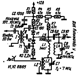
Fig.1
A schematic diagram of a parametric amplifier-Converter to produce a high intermediate frequency is shown in Fig. 1. It is balanced scheme on two varactors VI and V2. Equal in amplitude and opposite in phase to the voltage pump to the varactors is supplied from the secondary winding of the transformer T1, having a grounded outlet from the midpoint. The required initial voltage of mixing on the varactors is created using the divider resistors R1, R4, R5, R6. A trimming resistor R5 produces balanced Converter.
The input signal is applied through coupling coil L2 in the circuit L3C7, tuned to a frequency of 7 MHz. This circuit is connected to the anodes of the varactors through a coupling capacitor C5 and the inductor L1. An output circuit L4C8, tuned to an intermediate frequency of 144 MHz, is connected to the anodes of the diodes using a capacitor with small capacitance Sat. The frequency Converter has a high stability characteristics as voltage changes of mixing and pumping power. For example, lowering the voltage from 12 to 6 In the gain drops by 1 dB, and the amplitude of the voltage pump (in each section of the secondary winding of the transformer T1 from 1.5 V to 1.0 V) reduces the gain of only 3 dB.
For the most complete use of the capabilities of this amplifier-frequency Converter is required to apply УSW receiver with UHF gain 30...40 dB and providing efficient linear filtering conversion products.
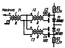
The parameters of the amplifier-Converter can be improved, if introduced into the pump circuit balun transformer (see Fig. 2). All three transformers are synonymous.

Fig.2
In the described amplifier-Converter, you can use the varactors DA or DB.
Literature
Publication: N. Bolshakov, rf.atnn.ru


