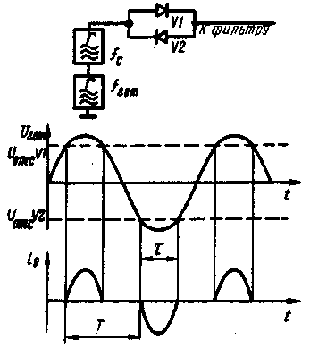
The mixer on the counter-parallel diodes (V. Poles. The mixer of the direct conversion receiver. -"Radio". 1976, № 12. p. 18-19.) allows high sensitivity and immunity to interference of direct conversion receivers, low voltage local oscillator at the antenna input. However, this mixer has the drawback that it requires a precise adjustment of the voltage of the local oscillator. In fact, to maximize the transmission coefficient of the mixer diodes should be opened only at the peaks heterodyne voltage Uгет (Fig. 1), and the ratio t/T of the current pulses d through the diodes should be approximately 0.5.
If the mixer uses silicon diodes with a voltage cutoff Uотс equal to 0.5, the amplitude of the heterodyne voltage should be 0.6...of 0.75 V. At lower values of the diodes will be almost closed, and at large almost all the time be open. In both cases, the transmission coefficient of the mixer is reduced.

Fig. 1
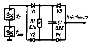
To eliminate the above drawback of the introduction into the mixer circuit automatic mixing, which when the voltage of the local oscillator would change the cutoff voltage of the diodes, thereby maintaining a constant duty cycle of the current through the diodes. A modified scheme of the mixer shown in Fig. 2. To improve the symmetry of the mixer is added to it even included two anti-parallel diode V3, V4, and chain automatic mixing R1C1 included in the diagonal of the bridge formed. The time constant of the chain R1C1 must be greater than the reproducible period of the lower audio frequencies, otherwise the voltage of mixing will be "modulated" output signal.

Fig. 2
The current pulse during the positive half cycle of the voltage of the local oscillator passes through the diodes V1 and V4, and during the negative - through V2 and V3. In both cases, these impulses cause the elements R1, C1, the voltage of mixing, proportional to the amplitude of the lo signal.
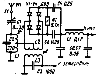
Describes the mixer can be improved (Fig. 3) by connecting the signal source and the load to the midpoint of the coil connection (L2) and the midpoint of the circuit of automatic mixing, respectively. While severely weakened the connection between the circuits of the local oscillator and the signal, since they are included in different diagonal balanced bridge.

Fig. 3
The input signal from the tap of the coil circuit L1C2 configured on the frequency of the signal is fed to the midpoint of the coil L2 connection. Coil L3 can be contour coil of an oscillator tuned to a frequency equal to half the frequency of the signal. If the local oscillator has a buffer amp, coils L2 and L3 can serve as winding high-frequency transformer wound on a ferrite ring. The voltage of the local oscillator mixer diodes V1 - V4 form a bridge rectifier, and the DC offset is allocated on a chain R1C4C5. The low-frequency signal is taken from the junction point of capacitor bias circuit and is supplied to the low pass filter L4C6C7 with a cutoff frequency of 3 kHz and further to the if amplifier. Since the output of the mixer there is no DC voltage, the coupling capacitor at the input of the low-frequency amplifier is not needed.
Both schemes mixer (Fig. 2 and 3) were tested in the direct conversion receiver in the range of 80 m (V. Poles. The direct conversion receiver. - "Radio". 1977. No. 11. S. 53-55.). It turned out that both silicon and germanium diodes suitable for mixer with automatic bias and give approximately the same results. You can use diodes (enumeration goes from worst to best) D18, D20. D-D. D--D. D2, D9, D311, CD, CDS, CD.
Measurement of parameters of the mixer showed that the transmission coefficient it has remained the same (receiver sensitivity is 1.5 mV - no change). Receiver sensitivity remained almost the same, and when the voltage amplitude of the local oscillator from 1 to 4...5 In (his controlled between the extreme terminals of the coil L2). The weakening of the local oscillator signal frequency of 1.75 MHz on tap of the coil L1 was 54 dB. Additional suppression of the lo signal occurs in the input circuit. The weakening of the AM interfering signal exceeded 80 dB AM signal amplitude of 0.1 V at a modulation depth of 30% and the detuning of ± 50 kHz gave at the receiver output the same voltage as the useful signal amplitude of 7 mV.
Author: V. Polyakov (RA3AAE), Moscow; Publication: N. Bolshakov, rf.atnn.ru


