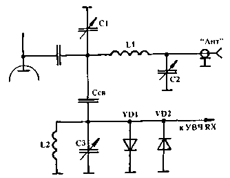
Fig.1
The scheme is simple and reliable in operation, however, as the experience of its use on my radio station, often in the range of 15 and 40 meters when you try to fine-tune the circuit, the selector L2C3 frequency of the receiving station the air is Packed with all sorts of interfering signals and noise. It happens because of the conversion of the powerful signals of broadcast stations nearby frequency ranges 16 and 41 m respectively on the non-linear resistance of the diodes VD1, VD2. To eliminate this drawback can simple reduction of CERs, but this leads to loss of sensitivity. Pretty effective measure against is the filing of a locking bias on the diodes in RX mode, but all the problem it solves. To completely get rid of this drawback I managed, gathering input circuit according to the scheme of Fig.2.

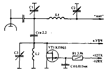
Fig.2
Circuit switching ranges not shown. The control transistor is performed by applying a voltage of appropriate polarity to the gate. Resistor R1 limits the current shutter when forward biased at a safe level, its value is not critical. Negative voltage on the gate resistance of the channel VT1 is very large, and it does not degrade the quality factor of the circuit, the selector L2C3.
An important advantage of the FET is the linearity of the channel resistance at low voltages, the source-drain, therefore, any conversion of frequencies on it not happening. In the transmit mode, a positive offset reduces the channel resistance to a few Ohms, which bypasses the input of the UHF RX and protects it from the signal transmitter. Control voltages may be different. For this type of transistor control voltage RX mode may be in the range (-10...-15V) is active, the TX - 0...15V.
Author: V. Vishnevsky (UB5AJS), Sumy. Publication: N. Bolshakov, rf.atnn.ru


