Fig.1
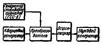
Before manufacturing a filter, you should pick up for the quartz. For the selection of quartz necessary to assemble the device, the block diagram of which is shown in Fig.2. In this arrangement, the frequency of the crystal oscillator, which establishes one of quartz, designed for filter, is compared with the frequency band of the generator in the suitability of quartz is determined by the received beatings.

Fig.2
As the frequency of the generator using the device GSS-6. You can collect for this purpose a special usecodepage generator, overlapping with some reserve bandwidth for future filter. Graduation he may not have at all, but you need a fairly high frequency stability. Crystal oscillator can be assembled in any scheme.
To obtain beats used any Converter cascade on multigrid lamp. On the heterodyne tube grid Converter is powered from a crystal oscillator, and a control - output voltage range of the generator. In the anode circuit of the lamp turns on the resistor value of the order of 200 ohms.
If you have an oscilloscope, the frequency of the beats is determined by the Lissajous figures using a graduated sound generator. If the oscilloscope, you can use another Converter and to determine the equality of the beat frequency and the frequency of the sound generator to zero-beat between them.
The filter manufacturer should begin with measurement of the frequency distribution of series and parallel resonances in each of the available quartz. The measurement should be repeated several times, trying to determine the resonant frequency with a precision of 10-20 Hz.
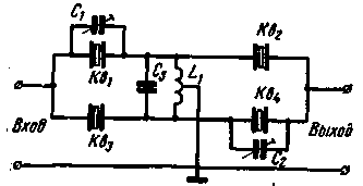
So according to the scheme shown in Fig. 1, it was possible to produce a filter with sufficient for SSB bandwidth, channel spacing frequencies of the two resonances at all oscillators must be more than 1000 Hz. Usually this condition is satisfied. Otherwise, it is necessary to reduce the capacity of cartegories, if possible, or assemble the filter on a different diagram.
Then you must use the same device (Fig.2) verify the absence of all visible quartz spurious resonances closer to 20-30 kHz from the main one. If the parasitic resonances are there, but less pronounced core 20 dB and above, and do not overlap between oscillators in frequency, they will not degrade the performance of the filter.
Now we need to postpone two quartz of equal frequency of the serial resonance, and the other two to rebuild to a higher or lower frequency. A good way to reduce the frequency of quartz in Amateur conditions do not exist. One of them is propilivanie grooves in the side faces.
However, deteriorating thermal stability of quartz and may appear spurious resonances. It is better to increase the frequency of the quartz. If they are metallized, this is achieved by careful erasing parts of the metal coating (uniformly over the whole area) using ordinary red (called ink) gum. Not to break the quartz when you wipe the metal coating, it should be put on a flat hard surface. If quartz is not metallized, to increase the frequency need polishing their plastic is very small (micron) sandpaper. Need to grind, moving the plate on the skin, but not Vice versa. Remember that sometimes just 2-3 plate movements on the skin to increase the frequency of quartz at 1000 Hz. In the process of restructuring quartz resonators may need more often to control the frequency of the series resonance.
To get the filter for optimal performance on SSB bandwidth (2600 Hz), you must rebuild the successive resonances of the two quartz 1800 Hz. In this case, the restructuring of the quartz must have a racing series and parallel resonances of not less than 2000 Hz. If done at the beginning of the measurements revealed that the spacing of the resonances below 2000 Hz but greater than 1000 Hz, quartz rebuild 0.9 magnitude frequency distribution. The bandwidth of the filter in this case will be less than 2500 Hz, but still sufficient so that the intelligibility of transmitted speech is not affected.
Coil L1 of the filter is placed in a core-type SB-3 and has an outlet from the midpoint. In order for the two halves of the winding were probably more of the same, and this is very important, the winding is carried out in two wires, and then the end of one of them connects with the beginning of another, thus obtaining the average output. The value of the inductance L1 should be such that when the capacitance of the capacitor C3 is equal to 15-20 pF, the resulting circuit was tuned to a center frequency of a passband of the filter. To specify the exact winding coil data L1 is not possible, since the average frequency can be different.
The filter is collected on the plate of insulating material, placing the quartz so that the left and right of the coil L1 was one quartz with greater frequency (Fig. 1 the quartz Q1 and QV more, and KV1 and KB3 - with less frequency). Trimmer capacitors C1 and C2, shown in Fig.1, the first stage filter settings should not be connected.
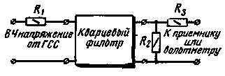
Configuring the assembled filter is as follows. The input filter serves voltage from the frequency generator (GSS-6 or other), and is connected to the output of a sensitive vacuum tube voltmeter or the receiver, as shown in Fig.3. If the indicator will be applied to the receiver, to be able to remove the frequency response of the filter, you need to put a stepped attenuator at the receiver input and to graduate its S - meter.

Fig.3
When used as a frequency generator device GSS-6 can determine the attenuation over his attenuators, maintaining a constant signal level at the receiver input. In any case, you have to be able to measure attenuation from 0 to 60 dB with an accuracy of 1-2 dB.
Crystal filter must be agreed with the generator and indicator. For approval are the resistors R1 and R2 (see Fig. 3). The resistance value of resistor R2 should be equal to the characteristic impedance of the filter. If the output impedance range of the generator is small enough, you should install the resistors R1 and R3 with the same impedance, otherwise the resistance R1 must be less than R2. Since the characteristic impedance of the filter is unknown, initially take R2=2 ohms. Resistor R3 and isolating, so its resistance must always be much larger than R2.
Attaching to the filter devices that remove points on the frequency response of the filter in the range of ±5 kHz from the middle of the bandwidth. Alternate selection of the filter capacitor C3 and resistors R1 and R2 to ensure that the characteristic bandwidth is made possible more flat. Valid small dips in 1-2 dB.
Stingrays bandwidth per atom configuration will be quite gentle. To increase their toughness alongside more high-frequency quartz included small capacitors. However, on both sides of the passband of the filter shows "tails" gentle slopes on its frequency response, reducing the suppression of the second side band.
To get possibly steeper slopes when the allowable amount of "tails", first connect only one of the shunt resonators of the capacitors, e.g., C1. The capacitance of the capacitor are selected such that the attenuation on the "tails" was 40-45 dB more than the bandwidth. Usually this is achieved when the capacitance Ci is $ 5-10 pF. Then include a capacitor C2, achieving reducing the size of the "tails". The capacitance C2 should be about 3-5 pF is smaller than C1.
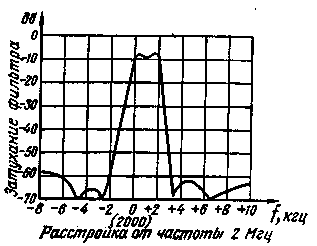
A properly configured filter should be on the characteristics of the four points of infinite attenuation: two above and below the passband. "Tails" located above the bandwidth frequency must be of equal size. If after the selection of the capacitors C1 and C2 filter bandwidth will become less flat, need more time to pick up the resistors R1 and R2. In this setting the filter ends. It remains to enclose the screen and again to check the frequency response.
High-frequency slope bandwidth filter, which used the same quartz, is steeper, so it is better to format with the help of this filter lower sideband, getting top in transformation frequency in subsequent stages. The attenuation of the filter in the passband of the order of 10 dB. This should be considered in the design of the pathogen.
In Fig.4 shows the response of the filter at a frequency of 2 MHz, configured as described. Its characteristic impedance is equal to 1000 Ohm, inductance L1 - 265 μh, the capacitance C3 56 pF, C1 = 12 pF, C2 - 9 pF. The spacing of the frequencies of the quartz Q2, KB3 and KV1, KV - 1800 Hz.

Fig.4
In conclusion, it should be recalled that in the pathogen, which will work made filter, the output impedance of the balanced modulator and the input impedance of the next filter in the cascade must be purely resistive and is equal to the characteristic .the resistance of the filter.
Literature
1. Polonskii A. F. piezoelectric Quartz technology, telecommunications, Gosenergoizdat, M-L., 1951.
2. Коsоwskу D. I., Proceedings of IRE, 1958, fevr., pp. 419-429.
3. Arnold, R. W., Alien S. R., QST, 1960, may, pp. 25-33
4. Robertson D. S., QST, 1964, July, pp. 58-59
Author: G. Zverev; Publication: N. Bolshakov, rf.atnn.ru


