In Amateur literature [1, 2, 3] gives several methods for configuring quartz filters. They are all about the same and are reduced to the preliminary layout for the purpose of measuring parameters of quartz and a rather large volume of cumbersome mathematical calculations. However, after mounting, the amplitude-frequency characteristic (AFC) of the filter, as a rule, are far from desirable. It is evident, the variation filter elements and difficult-to-count and erection of tanks. As a result have to spend a lot of time for the correction of frequency response selection of the capacitances of the filter and matching resistors.
Based on the above, the idea to abandon the settlements in General. Because their results are flawed and instead of piloting to restricted health check, in fact, quartz resonators (for this is quite simple oscillator with one transistor and oscilloscope), and the basic settings of the filter to produce, using condensers of variable capacity (PBC).

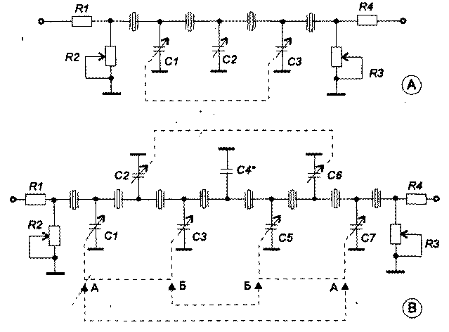
Fig.1 Quartz filters with parallel capacitances
Arrows AA and BB shows a second variant of the inclusion of KPE. The resistors R1, R4 (0... 300 Ohm) installed if you have large emissions on frequency response. The capacitor C4* is chosen in the range from 0 to 30 pF.
To minimize the number of capacitors were chosen scheme of filters containing only parallel capacitance, Fig.1. Since the filter is symmetric (with respect to their input-output), it was possible to use dual KPE from broadcast receivers with a capacity of 12 - 495 pF. In addition, you will need one pre-scaled in pF, single-section variable capacitor.
Filter setup is the following
For settings, you may need a unit for measuring the amplitude-frequency characteristics of the H1-38 or the like. I use a oscilloscope and a homemade console (see below).
Initially, all capacitors are installed in the position corresponding to the capacity of 30 to 50 pF. Controlling the frequency response of the filter on the screen of the device, rotation of capacitors within a narrow range to achieve the required bandwidth. Then, by adjusting the variable resistors (use only non-inductive, for example, JS4-1) at the inlet and outlet of the filter, try to align the top of the AFC. The above operations are repeated several times to obtain a desired frequency response.
Further, instead of each individual partition KPE, solder pre-scaled capacitor, which try to optimize the frequency response of the filter. On its scale determined by the capacity of the DC capacitor and produce a replacement. Thus, all sections KPE, in turn, are replaced by fixed capacitors. Similarly, the act with variable resistors, which subsequently replace the constant.
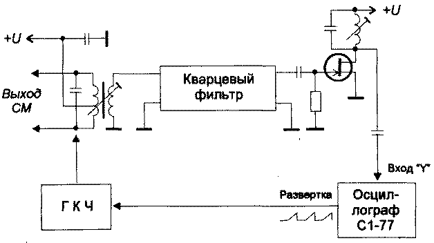
The final bringing of the filter is directly in situ, for example, in the transceiver. After installing the filter in the transceiver may require correction of the values of these resistors, in this case, to match the filter with the output of the mixer and the input of the HRC, the sweep and the oscilloscope must be connected according to the scheme shown in Fig.2.

Fig.2 Connect a quartz filter for final tweaks
According to the method described above was made a few filters. We note the following. Configuring three or four crystal filters at some skill it takes less than an hour, however with 8 crystal filters time is much higher. Thus, prior attempts at first set of two individual 4 crystal filters, and then their convergence is proved to be fruitless. The slightest variation of their parameters (and this is always the case) leads to a distortion of the resultant frequency response. It is also interesting to note that theoretically equal to the capacity (for example, C1=C3, in Fig. 1A; C1=C7; C3=C5 in Fig.1B) after adjusting graded KPE for optimal frequency response had a noticeable variation.
In my opinion, the advantage of this technique is its visibility. The device is clearly seen how changing the frequency response of the filter depending on changes in the capacitance of each capacitor. For example, it was found that in some cases it is enough to change one capacitor (via a relay) in order to change the bandwidth of the filter without much deterioration in its Squareness.
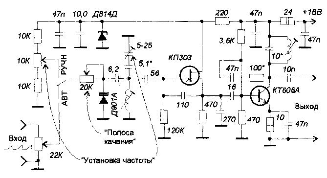
As noted above, the filter settings used oscilloscope S1-77 and redesigned the console to measure the frequency response [4].
Why S1-77? The fact that its side wall has a slot on which there is a sawtooth voltage sweep generator. This can simplify the console itself and to exclude from its scheme, the sawtooth generator (FPG). So, no need for additional synchronization and it becomes possible observation of a stable frequency response at different scan durations. Obviously, you can adapt and oscillographs other types, may be after a little refinement.
Since, the simplified prefix is used only when working with quartz filters near the frequency of 8 MHz, all other subbands were excluded from it.
Also, in the console, you will need to slightly increase the output voltage. It's enough to alter the output stage is in resonance. It has to be tuned in resonance each time after his exit will connect the new filter.
Scheme modified consoles is shown in Fig.3. Due to the insertion of parasitic capacitances all connections between the test filter and the prefix should be short conductors of length at most 10 cm.

Fig.3 Attachment to the oscilloscope to configure quartz filters
Literature
1. V. Galneryus. The series of articles "Quartz filter" Log "Radio" № 1, 2, 6, 1982, No. 5, 7, 1983
2. S. Bunin, L. Yailenko "Handbook of shortwave" ed. "Technology" 1984
3. V. Drozdov "Shortwave radios" ed. "Radio and communication", 1988
4. The magazine "Radio", No. 5, 1993 "sweep Generator"
Author: F. Sharapov, RA4PC Leninogorsk; Publication: N. Bolshakov, rf.atnn.ru


