Ham necessary and safe power supply 220 V, with which can be developed and tested independently collected the device and repairing devices industrial manufacturing.
Such a power source when power from the lighting circuit 220 In need to support the work when the load current up to 10 A and to have the opportunity to back power to ensure that in case of need, trouble-free operation. It may be necessary, for example, in rural areas, when the supply voltage is unstable or intermittent.
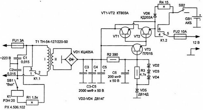
In Fig. 1.1 a circuit diagram of a power source that meets all these requirements.

Fig. 1.1. The electrical circuit of the power source with a current capacity in loads up to 10 A.
A voltage regulator transistor VT3 and the Zener diodes VD2-VD5 is assembled by the classical scheme.
The power supply is carried out "manually" switch (toggle switch) SB1. When power to the relay K1 it is triggered and closes the contacts K1.1 chain the primary winding of the power transformer T1. Rectified by a diode bridge voltage VD1 is supplied to the stabilizer of the source, then the current amplifier transistors VT1, VT2 and further, the device load.
At the same time on a car battery (battery), which serves as backup power supply, receives a charging voltage across the diode VD6 and a current limiting resistor R4. A small current to recharge the battery depends on the battery is low, given its greater intensity 55 Ah, outputs battery failure even during long-term (several days) mode of recharging.
When this switch SB2 can be forced off the battery from recharging.
In the emergency mode (no voltage lighting 220 V) relay K1 de-energized, and the voltage from the backup power source (battery) is supplied through the closed contacts 5 and 6 of the group of contacts K1.2 relay K1, bypassing a voltage regulator, assembled on the elements VT1, VT2, VT3, VD2, VD3, VD4, VD5, R2, R3. To protect the source against overvoltage and short circuit protection are fuses FU1 and FU2, respectively installed on the inlet and outlet the power source.
If necessary, a reserve power is not, then the battery is not connect and use the device as a powerful source of stable power.
The housing is made of fiberglass, but may be made from another dielectric material.
Transistors VT1, VT2 can be replaced by CT, CT with any letter index. It is desirable to apply these transistors in a metal case with the diameter of the "hats" of 23.5 mm. They are mounted on heat sinks with cooling area of at least 100 cm2, insulating heat removal from the device body. The transistor VT3 can be replaced by KT815, KT817 with any letter index.
The transformer T1 standard with a power output of not less than 100 watts shall to provide an alternating voltage in the secondary winding (under load) V. 14-16 This voltage gain from the terminals 7 and 16 of the transformer TN-54-127/220, must be installed jumper between pins 8-9, 10-11, and 13-14. Primary winding of the transformer T1 is pins 1 and 2.
Battery - standard battery with nominal voltage of 12 V. the Relay K1 - on voltage response 200-220 In two or more groups of contacts and the switching current is not less than 3 A.
Mains fuse FU1 type. EAP-1-3, PC-30-3 for a current of 3 A.
Fuse FU2 on the current 10 A type WPC-1-2.
Diode rectifier bridge type CCA, CCA or assembled from discrete items diodes D, D with any letter index. Diode VD6 can replace KD202 CD, CD with any letter index and similar. Zener diodes VD2-VD5 is desirable to set in accordance with the procedures described in scheme. Their parameters determine the stabilization and output voltage level.
Capacitors C1, C2 type K40-U9, K10-17 or equivalent, designed for a working the voltage of at least 250 V.
Oxide capacitors type K50-ZB, C50-24 or similar.
Fixed resistors R2, R3 - type MLT-0,5. The resistors R1, R4 type sew-10,AD-10.
Switches (toggle switches SB1 and SB2 any suitable, for example, TB2-1.
Author: A. P. Kashkarov


