


")

In Amateur practice there is often a need at power supply with an output voltage of the automotive on-Board network. In Fig. 1 shows a schematic diagram of the power supply.
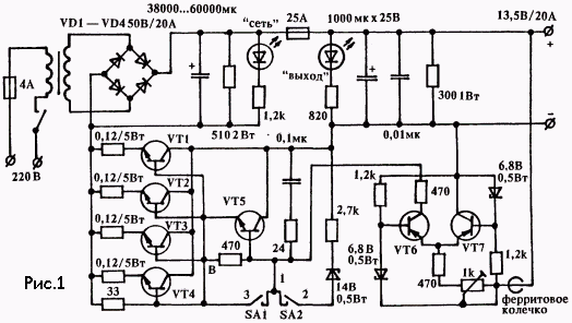
The secondary of the transformer must be rated for a current of 20A and a voltage of 20V. The diodes of the bridge are mounted on the heat sinks, it is better to use power diodes with Schottky barrier. The diodes should be on the operating voltage below 50 volts and the operating current of at least 20 amps. Stabilizer with fault protection transistors VT1… VT7. The output voltage is set trimming resistor 1kOhm. The error signal amplifier is performed on the differential cascade VT6, VT7. A repeater on a composite transistor VT5 regulates the control transistors VT1…VT4, in the emitter circuit which included leveling resistors of 0.12 Ohms, providing a uniform current distribution on all four transistors (5 each).
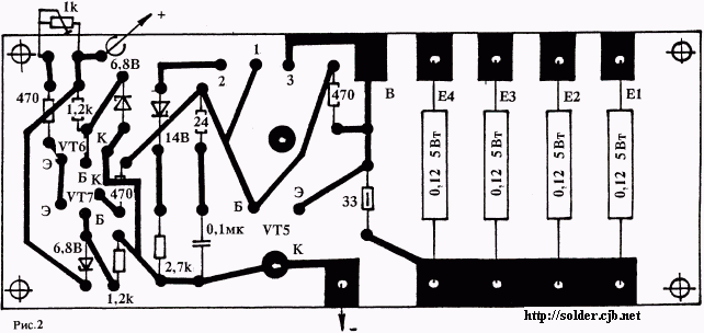
The printed circuit Board of the device shown in Fig. 2. The network rectifier, filter capacitors and transistors VT1…VT4 is installed outside of the Board. Collectors VT1…VT4 galvanically connected to the housing that allows you to use the chassis as a heatsink without insulating strips.
Publication: www.cxem.net