


")

The proposed self SMPS (switching power supply) has a small size and high efficiency. Its feature is that the magnetic core pulse transformer works with entering into the saturated region. When designing a self SMPS in most cases, powerful transformer used in a linear mode and a low-power switch - mode saturation of the magnetic circuit. The individual windings of these transformers are connected in-series with one another and a current-limiting resistor, and there is a positive feedback circuit (PIC).
The disadvantage of this solution is the increased heat in the resistor. The desire to reduce the power dissipated by this resistor, in most cases, leads to increased heating of the switching transistors and reduced efficiency. Low efficiency is forcing developers to pay attention to other circuit solutions converters, such as the Royer oscillators. They have a transformer from saturating the magnetic core, and low-power switching transformer and current limiting resistor in them missing.
However, through the switching transistors in the moments of commutation current flows, pulse amplitude which can exceed 3…20 times the average value of current consumption. This circumstance not only dictates the selection condition of transistors with a large stock of current, but also manifests itself in increased heating. The efficiency of this SMPS is approximately 50% when the output power up to 30 watts. Efficiency can be increased by including in the emitter circuit of the switching transistors of the low-impedance resistors. That is exactly what is done in the SMPS, the scheme of which is shown in Fig. 1.
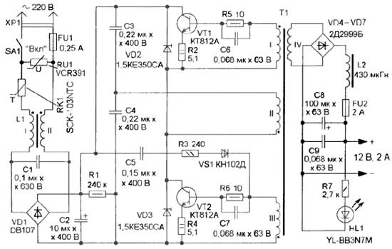
Fig. 1
At first glance it may seem that this would lead to increased release of heat on these resistors. But thanks to these resistors, a local negative feedback (EP) current limiting the collector current of the transistor at its sharp increase. As a result, the amplitude of the collector current at the moments of switching transistors in a few times is reduced, increasing the efficiency of the SMPS. In the proposed SMPS heating of the switching transistors and the transformer compared with the variant in which these resistors are missing, decreased about three times, respectively, increased reliability and efficiency.
Specifications Voltage, 220 ±20% The output voltage of idling, In 15 The output voltage at maximum load, In 12 The maximum load current, And 2 The frequency in the idle kHz 7,3 Conversion frequency at maximum load, kHz 6,7 The idle current of the SMPS, mA 19 The maximum power consumed by the load, W 24 Maximum efficiency (at maximum output power), % 84 The amplitude of the output ripple voltage, not more, mV 22 Overall dimensions, mm 110x73x25Mains voltage is supplied to the SMPS through FU1 fuse-link, which, together with the varistor RU1 protects the elements of the SMPS from high mains voltage. The thermistor RK1 limits the pulse of current when charging the capacitors C2-C4 at the moment of switching SMPS. Mains voltage via the noise filter L1C1 is supplied to the diode bridge VD1, where it is rectified and then smoothed by the capacitor C2. Elements C5, R3, VS1 form a chain, which facilitates the starting of the Converter when it is turned on.
Damping diodes VD2, VD3 limit to a safe value the amplitude of the pulse voltage at the collectors of the switching transistors VT1, VT2. The dissipation in these transistors are small, so they are used without a heatsink. In the most difficult mode transistors are heated to 50°C. the Resistors R2, R4 to form a chain OOS current, a circuit R5C6 and R6C7 are designed for forced switching transistors. Output AC voltage diode bridge rectifies the VD4-VD7, L2C8C9 - smoothing filter, and the throttle provides inductive response of the filter, which is necessary for reliable start up of the Converter. Installation at the output of the rectifier capacitors 68 NF and more will lead to a launch failure. HL1 led indicates the presence of output voltage. All the details SMPS are mounted on a circuit Board of one-sided foil fiberglass, a drawing of which is shown in Fig. 2.
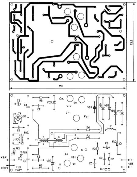
Fig. 2
To improve cooling of the MOSFETs in the circuit Board beneath them made the vents. The inductor L1 and transformer T1 are fixed with screws. Once these screws are inserted into the holes of the Board at which the side parts should be worn segments of PVC pipe. Then set the choke, transformer and press them to the Board using plastic washers. The transistors are fixed with screws on metal posts, and then soldered to the Board. Fuse FU1 consists of two tin-plated pin is pressed into the Board, between which is soldered a copper wire with a diameter of 0.03 mm Outside his close cut PVC pipe to protect it from mechanical damage, and in case of emergency, to protect the SMPS components from splashes of molten metal. For fuse FU2 on the Board mounted plastic holder. The appearance of the assembled and plugged in the SMPS shown in Fig. 3.
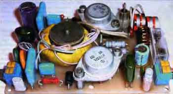
Fig. 3
A dinistor CND replace on DB3, DB4, or any of a series of KN, diodes 1.CASE 1 interchangeable.CASE, 1.CASE, 1.CASE, diodes DB - KDA, KDA-CDV, CDA, CDB. Led YL-BB3N7M can be replaced by any compact of any color glow with a working current up to 20 mA. After the experiments, the author found that the transistors CTA interchangeable on CTA. When using transistors TA, CTB, CTA heating was increased, but was within the acceptable range, but they have another case that would require changes to the layout of the circuit Board. The thermistor SCK-103NTC can be replaced by MZ92-P220RM, MZ92-R220RM, MZ92-P330RM, MZ92-R330RM, varistor VCR391 - JVR-10N361K, JVR-14N361K, JVR-20N361K, JVR-10N391 TO, JVR - 14N391 TO, JVR-20N391K, JVR-10N431K, JVR-14N431K.JVR-20N431K. The inductor L1 is wound on the yoke MNM size CHH and contains 10 turns double-folded wire MGTF of 0.12 or PELSHO of 0.3.
The inductor L2 is wound on the yoke MNM size CHH, coil contains 24 round wire PETV or sew-2 with a diameter of 0.85 mm For transformer T1 applied magnetic MNM-AND CHH ferrite (measured by the author permeability was 1885, and the induction of deep saturation - 0.38 T). It is permissible to apply a magnetic MNM, MNM-17, MNM-39 size Chg. For winding can be applied wire PETV, sew-2 or PELSHO, windings I and III each contain 8 turns of wire with a diameter of 0.3 mm, winding II - 351 round wire with a diameter of 0.45 mm, winding IV - 33 coil of wire with a diameter of 0.85 mm.
The pre-edge magnetic grind off and wound two layers of varnished cloth or one layer of cloth insulating tape. The wires of the windings are placed tightly to the magnetic circuit. The windings I and III is wound simultaneously in the first two wires with an interval of 3…5 mm between the wires to prevent breakdown. Then the winding is impregnated with shellac and wound two layers of varnished cloth. Next - single layer winding II, stacking wire "round". Between the beginning and the end of this layer must be a distance of 6…7 mm, wire clips and impregnate the winding shellac. Then lay a layer of varnished cloth and similarly wound around the second and third layers of the winding II, and then lay two layers of varnished cloth or adhesive tape. The latter winding is wound IV, impregnate her shellac. Then two or three layers of insulation tape to protect the windings against mechanical damage. When establishing remember that the elements of the SMPS are under dangerous voltage, so all replacement items when disconnected from the network device.
Before first power source to the network, you should verify the installation to verify that the collected product conforms to the schema. After that, take out the fuse-link FU2 from the holder and include the SMPS in the network. If you enable auto generation does not occur, then increase the capacitance of the capacitor C5 to 1 µf or install a resistor R3 resistance of 120 Ohms. If the idle current of the SMPS will be more than 40 mA (measured between mains filter and diode Assembly VD1), it means that the induction of saturation of the magnetic circuit is much less than 0.38 T. In this case it is necessary to proportionally increase the number of turns of all the windings of the transformer T1. To increase the number of turns should be at least 10…15 %, and optionally more. During normal operation of the SMPS transformer T1 must emit a low whistle.
In conclusion, it should be noted that the basis of this ARIA is the transformer T1, so if you need to apply magnetopause a different size or get another power, it is necessary to recalculate all the elements. The easiest thing to do on the computer, using the author's program Converter 4.0.0.0, http://www.moskatov.narod.ru/ Converter.html
Author: E. Moscato, Taganrog, Rostov region; Publication: www.cxem.net