The article will focus on more recent fluorescent with the usual threaded socket, so-called energy saving. If you there is such a lamp, the worn or damaged, the contents of her the cap will help to solve a common problem - where to get small, economical and cheap AC adapter. Attempts to solve this problem many can recall several publications in the magazine "Radio" under the conditional name "Network "Krona". In the electronic unit energy-saving lamps contain most of the details of such source power, it is only necessary to add the output circuit.
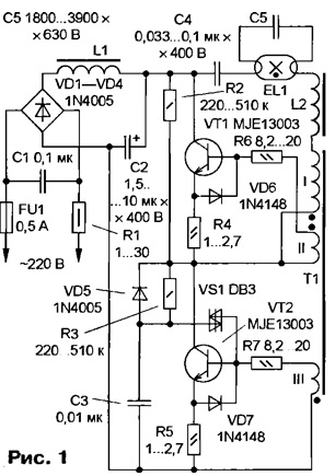
In the threaded cap of a fluorescent lamp that replaced the conventional lamp filament is a round printed circuit Board on which is assembled Converter for its power supply. The scheme is similar to the lamp shown in Fig. 1. Of features can to mention a specific output circuit with inductor L2, the node on startup symmetric diacs VS1 and current control switching power the transistors. The startup circuit is required because the generator feedback current itself does not start. The elements C1, R1 and L1 to prevent the spread for mains interference arising from the operation of the generator.

No wonder that the scatter of the values of the elements specified in the scheme, " he exists for lamps of different power and different manufacturers, of course, given the fact that the paired elements (e.g. resistors R2 and R3) have the same values. The same applies to diodes with transistors is indicated in the scheme only the most common types. The inductor L2 is assembled on a miniature Of W-shaped magnetic core of ferrite with exterior dimensions 10...15 mm, sometimes with a small gap. Its winding contains...240 350 turns of winding wire with a diameter of 0.2 mm.
Transformer T1 is made on a circular ferrite magnetic core outer diameter 8... 10 mm and a height of 3...5 mm, the primary winding (I) contains 6...10 of turns of the winding II and III 2...3 coils, and the wire can be as the wrapping diameter of 0.3...0.4 mm, and the conventional circuit. Choke L1 - fifteen to twenty turns of winding wire diameter of 0.5 mm, wound on a small ferrite core. Operating frequency of the generator is determined mainly parameters of the transformer T1 and rated load equal to 40...60 kHz.
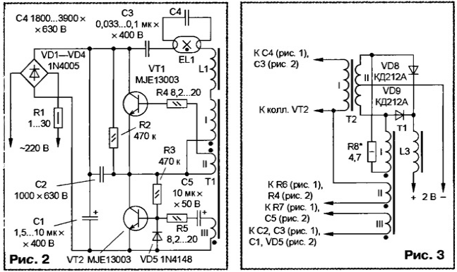
There is another version of the Converter that is used most often in the most low-power lamps. Its scheme is shown in Fig. 2. The main difference from previous options - the lack of the startup circuit. The soft mode excitation is created here due to priotkryvaya transistor VT2 current through resistors R2 and R3. The launch also contributes to the capacitor C5, added impetus to the base current of the transistor VT2 at the time of power on. In addition, in the low-power lamps usually there are no suppression circuit and even fuse.
How to use this product? The options can be many. The author, for example, using such a Converter has managed to turn the battery the shaver Hitachi ' fed from a network of 220 V. For this we used the fee containing part no mpsa42 transistors in the buildings of to-92 and the most the other elements for surface mounting. Basically, the circuit device corresponds to Fig. 1. Refinement is shown in Fig. 3. First of all fees you need to disassemble the conclusions of the lamp, the capacitor C5 and the inductor L2, and unsolder the terminals of the primary winding of the transformer T1.
The inductor L2 should be carefully disassemble and remove the old coil and strip, creating the gap, if any. It should be recalled that during disassembly very easy to break W-shaped magnetic core. Therefore, if it is glued, you may not to help even heating of the ferrite, and then recommend immediately remove frame winding, and then to make new cardboard. A magnetic circuit with frame used for the manufacture of the transformer 12. The parameters of windings of the following: primary I - 400 turns of wire sew-2 0,12, secondary II (at an output the voltage of 2 V) - 9+9 turns of wire sew-2 of 0.6. To wind the secondary winding it should, as usual, wire, folded in half, and do not forget about good winding insulation (minimum of 2-3 layers of varnished cloth). The Assembly of the transformer T2 it is easiest to implement using strips of varnished cloth or even duct tape, elastic stretched along the outer contour pressed against each other halves of the magnetic core. Glue them undesirable, and suddenly you'll need to disassemble? Can to try to wind a transformer without disassembling the magnetic circuit, using the Shuttle. The finished transformer is sealed in fee to his former place or have arbitrarily. The inductor L3 is wound on any ferrite the podstroechnik. Its winding contains 15...20 turns of wire sew-2 diameter 0,6...0,7 mm.

Changes in the circuit of the primary winding of the transformer T1 is caused by the desire to move from current feedback, which is very sensitive to the load, to return connection output voltage. Generator feedback voltage stable in performance, regardless of changes in the output voltage. If the generator is not start (possible incorrect phasing), simply reverse the ends the primary windings of any transformer. Since the output rectifier diodes VD8, VD9 operate at a current close to the limit, it is desirable for the best cooling install them on dural plate possible in the selected body area. The penultimate operation - selection highest denomination resistor R8, which provides reliable starting of the Converter when any load and nominal operating frequency (50...60 kHz). Resistance resistor R8 is selected in the range from 1 to 30 Ohms. Finally, measure the weekend the parameters of the resulting power source, controlling the degree of heat to elements. In the author's version managed to get the power output of approximately 2...3 W (output voltage of 2 V at load current 1...1.5 A).
It remains only to mount an established source in the housing of the powered device. The above unit was able to place in the body of the shaver in place the AA battery and charger.
A similar power supply can be done on the basis of the Converter, assembled according to the scheme of Fig. 2. Recently appeared lamps with transformers, circuit which differ from those shown in Fig. 1 and 2 - on field-effect transistors and even integrated chips. They can also be used to create source power - you only need to enable the transformer T2 (Fig. 3) instead of the lamp EL1, nothing more without removing or altering. However, this will not return the link current, which the Converter can operate normally with only constant load. If you must use a Converter ultimate the power switching transistors preferably set to a suitable the heat sink.
Author: V. Stryukov, Kaliningrad


