It is often necessary to feed a device of the bipolar stabilized voltage. While suitable for the manufacture of such source the power transformer has only one secondary winding. How can that be? The answer to this the question you will find, after reading the article published here.
Offer a simple two-pole power supply is made on the basis of integral stabilizer CREA.
Distinctive features of this device:
- the minimum number of parts;
- no allocation is required in the secondary winding of the mains transformer;
- regulation of the output voltage within %5...15 V when the output current up to 1 A.
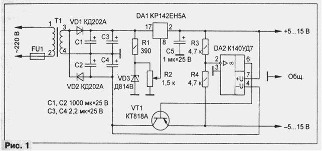
Schematic diagram of the power supply with a voltage regulator is shown in Fig. 1. Remove from the secondary winding of the transformer T1, the voltage 13...15 In supplied to rectifier voltage doubler, assembled on the diodes VD1, VD2. Capacitors C1-C4 filter provides smoothing the ripple of the rectifier.

Bipolar voltage stabilizer based on a single chip with DA1 voltage stabilization 5 is executed according to the scheme of Fig. 12 in [1]. The difference is additional adjustable reference voltage source VD3R1R2 [2].
The power transformer T1 must have a minimum size and weight and to provide the necessary load current at a voltage of 13...15 V. If a suitable the transformer could not be found, you can use the recommendations given in [3], and make it yourself.
Diodes VD1, VD2 - series KD202 with any letter or other rectifier with the value of the average forward current of 3 a at a voltage of not less than 25 V.
Capacitors C1, C2, C5 - C50-35, K50-16, K50-6 with a working voltage of 25 V; C3, C4 - tantalum, a capacity of 1 μf, can be replaced by oxide with a capacity of 25 μf, and if the length of the wires connecting a voltage regulator with filter capacitors C1, C2, does not exceed 100 mm, excluded [1].
Transistor VT1 - series KIT with any letter or other series with the allowable current collector is not less than 3 A.
Instead of Oh CUT approach(R)UA(or B), COD (when using the latter will require correction of the PCB). Resistors R1, R3, R4 - MLT-0,25; R2 - JS4-1 or similar.
Chip CREE interchangeable on K142EN5A, and K(P)TV.
The design of the power source depending on the applied elements (transformer, diodes, capacitors, etc.) can be arbitrary. In author embodiment, the device is assembled in the housing from industrial unipolar power supply unit PSU-12/10, from which previously removed Plata, capacitor filter and two rectifier diodes.
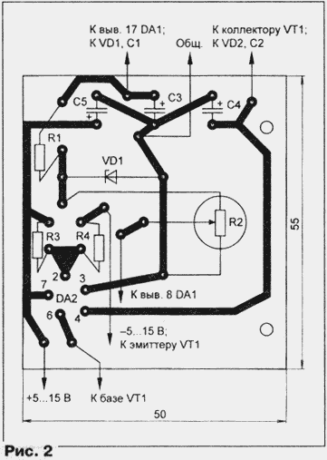
The main part of the elements of the stabilizer is placed on the circuit Board (Fig. 2) from unilateral foiled fiberglass 1.5 mm thick. Capacitors C1, C2 are located separately and connected by conductors to a rectifier and main Board.

The fees of the stabilizer is chosen so that it was easy to install on the Board of BP 12/10 and fasten it with screws. The hole diameter of 10 mm is used for fastening of the resistor R2; opposite him in the body also drilled hole the shaft of the variable resistor.
Transistor VT1, DA1 chip mounted by using a mica strip on heat removal from BP-12/10, for what it is additionally drilled two holes and threaded M3.
Made of non-defective parts of the power unit in the building does not need.
With proper selection of the transformer T1, the chip DА1 and resistance resistors R1-R4, the output voltage can be increased to 25, and introducing additional elements on the recommendations given in [1], significantly to increase the load current.
The Zener diode VD3 can be eliminated. The upper (the scheme) conclusion resistor R1 must be connected to the pin 2 of the chip DA1, and the resistance variable resistor R2 to reduce to 1 kω. The capacitor C4 is also not required, but to reduce the ripple useful between pin 8 of the chip DA1 and General wire to include an oxide capacitor of at least 47 µf working on the voltage of at least 10 V.
Literature
Author: V. Kobrin, p. seshcha Bryansk region.


