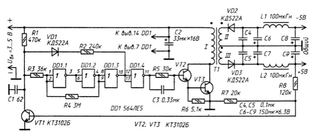
The described stabilizer simple, contains a relatively small number of elements and, as shown by observation of the work, has good technical characteristics. He keeps working without degradation of performance when the input voltage from 3 to 15, it can be used in many other devices requiring stabilized bipolar power source.


The master oscillator the stabilizer is made with the use in it of the timing capacitor C1 and Schmitt trigger, made in the elements of chip LE (DD1). When the output element DD1.3, there is the voltage is high, the diode VD1 is in the closed state, and the capacitor C1 is charged by the input source the voltage across the resistor R1. As soon as the voltage on the capacitor reaches threshold trigger, state trigger abrupt changes to opposite and on the output element DD1.3 sets the voltage low level. Now the diode VD1открывается and condenser. 1 discharges through the diode, the resistor R2 and the output item DD1.3. When the voltage on the capacitor decreases to the threshold off the trigger, he will switch to its original state and the process of operation of the generator again.
The output voltage stabilizing circuit VT1, R7, R8 are as follows. While the output "+5 V" voltage is small, the transistor VT1 is closed and does not affect the operation of the generator - the output of the maximum possible pulse duration and pause between them minimum. When the output voltage the specified value, the transistor VT1 open, the charging time of the capacitor C1 is increased, and the time of her discharge, on the contrary, reduced. Accordingly, the pulse width of the opening composite transistor VT2VT3, reduced pause between them increases, causing the output voltage stabilizing.
In the stabilizer you can use the IC series 564, C, CR containing four of the inverter.
Diodes - any high frequency. Capacitors C2 and C6-C9 - oxide K52-1, K50-6, C50-16, and the rest - K10-17, km-5, km-6. Transistors CTB interchangeable transistor Assembly NT. Inductors L1 and L2 - DM-0,1 100 µh inductance. Transformer T1 is made on the magnetic core size CHH,5 ferrite MNM. Each of the windings of the transformer contains 100 turns of wire PELSHO of 0.1, but the primary is wound in two wires.
Establish the unit in this order. The output of both shoulders stabilizer (between pin +5 V and -5 V) include a load resistor resistance 500...600 Ohms. Then the input device serves supply voltage 5 In and voltmeter to measure the output voltage. Equality of input and output voltages achieved by selection of the resistor R8.
After that input the voltage is reduced to 3 In and also control the output voltage the stabilizer. In case of failure of generation of the clock generator choose the resistor R2. On this adjustment of the device can be considered finished.
Author: A. Safronov


