


")

Just say that to make BP and another maximum output voltage and current, will be described later, why and how to do it (in the scheme considered 20 volts 5 amps).
In this structure can be applied one of the following displays from cell phones Siemens A70, A52, A55, C55 perhaps even from some of the others are unknown to me.
The location of the findings from these displays are depicted in figure
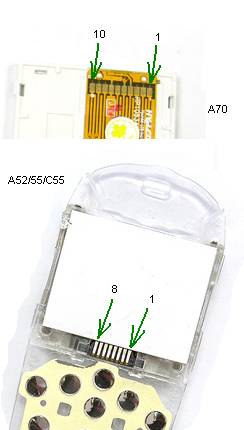
So, for adjustment and we'll need a PSU
1. Tester (voltmeter, ammeter) and it is desirable that he measured quite accurately.
2. Frequency (accuracy is not particularly necessary, it is necessary to measure 1 kHz +/- 3 Hz)
3. The dummy load (resistor 5-10 Ohms with a power dissipation of 2.5 Watts)
4. Straight arm.
Now a little design
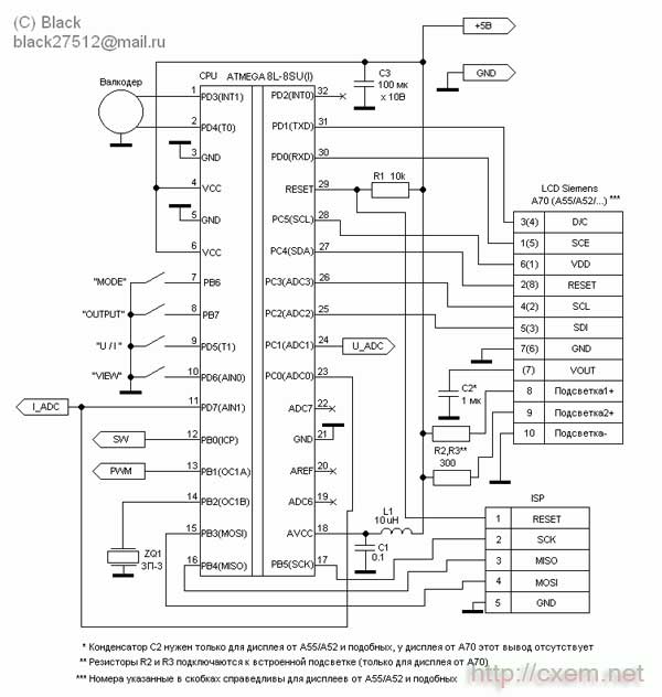
All the controls in the scheme implements a microcontroller ATmega8, he clocked from the internal RC-circuit as evidenced by the absence of quartz :) Its internal ADC it measures the output voltage and current, internal PWM modulator controls the output voltage. Through the internal comparator is implemented current protection (protection against short circuit). Even through the ports, the controller controls the relay, polls the buttons and valcoder, displays the image on the display.
Valcoder can be applied to any design (for example I took off the front panel of the car radio Sony :) ). You can make from an old computer mouse (ball, although across the infa and about how to make and optical).
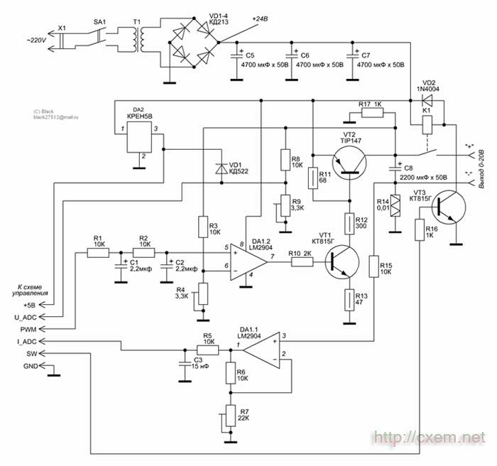
The transistor VT2 is installed on the radiator area is based on the maximum power you need. For example, when the voltage of the 24V transformer and the supply to the load at 10V 1A we obtain: P = (Uтрансформатора - Uнагрузки) x I of the load; (24V-10V) x 1A = 14 Watts!
Programming
There are two firmwares, they are the same, but are designed for different displays (for A70 and all the rest).
To flash the controller as in-circuit, and separately for the programmer. Don't forget to flash the EEPROM area (if not flash your PSU will not work correctly). I recommend to flash the controller separately from the scheme, because this device is powered from the mains during the flashing process can break down the controller/programmer/PC port. However, if applied to the controller in the planar case, it is more convenient to in-circuit flash. But there definitely need to comply with security measures, namely: between the programming device, PC and the device must be very reliable ground (common rail), connect/disconnect the programmer from the device to produce only taken out with a fork (the BP) from the wall outlet, do not trust the network switches filters! They are often only on one of the network cables!
And so with IOS look after the firmware code is still necessary to set the configuration bits. Through careful with them, especially with CKSEL, RSTDSBL: SPIEN! When it was installing the controller can stop seeing each other for a programmer!
Bits set in the following order:
;BootLock12 = Programmed (1)
;BootLock11 = Programmed (1)
;BootLock02 = Unprogrammed (1)
;BootLock01 = Unprogrammed (1)
;Lock2 = Programmed (0) ;)
;Lock1 = Programmed (0)
;
;RSTDSBL = Unprogrammed (1)
;WDTON = Unprogrammed (1)
;: SPIEN = Programmed (0)
;CKOPT = Unprogrammed (1)
;EESAVE = Unprogrammed (1)
;BOOTSZ1 = Unprogrammed (1)
;BOOTSZ0 = Unprogrammed (1)
;BOOTRST = Unprogrammed (1)
;
;BODLEVEL = Programmed (0)
;BODEN = Programmed (0)
;SUT1 = Programmed (0)
;SUT0 = Programmed (0)
;CKSEL3 = Programmed (0)
;CKSEL2 = Unprogrammed (1)
;CKSEL1 = Programmed (0)
;CKSEL0 = Programmed (0)
Now the adjustment device
Thereafter (feed network voltage) check the voltage on the output of the diode bridge (in my case should be 24V) and the voltage at the 3rd output DA2, there in any case, it should be 5V.
While the display may not appear, this is normal. The first thing you do is configurable settings LCD. To do this you must disconnect the mains voltage and wait until the discharged filter capacitors. Next, hold down all 4 buttons (press and hold), apply mains voltage. BP needs to squeak 4 times (if not, then probably not true stitched controller or something is not right with his power/signal RESET or ZQ1). Prapisau 4 times, the display may be prompted with a message
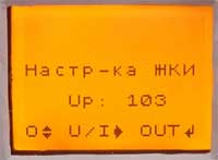
This is the 4th option on the account, clicking on the U/I will go for option number 1 (you will hear one long beep), press again the transition is performed to the 2nd (two signals), and so up to 4 and in a circle, changing the settings are applied to the display (visually). The parameter change is made by the pen of valcoder, change is accompanied by a beep. To remember settings and return to normal mode press OUT.
Next, you must configure the analog part of the circuit:
To do this, just unplug the PSU, press and hold the MODE and VIEW, and apply power. You will see on the display the following:
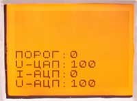
The threshold speaks about the protection status K. Z., 0 - the current in normal 1 - current is exceeded, the U-DAC - state PWM modulator (the magnitude of the set voltage), the I-ADC - the current measured current, U-ADC - current measured voltage. Are all the buttons: OUT / MODE - control the output relays, VIEW / U/I - control Squeaker (for testing).
Methodology the following settings: tap OUT (enable relay), set valcoder value U-DAC 500, connected to the output of the PSU voltmeter and set resistor R4 half the maximum output voltage (in my case is 10 volts). Further, a resistor R9 to achieve the same readings of the U-ADC and U-DAC (i.e. that would be on U-ADC was also 500). All the tension is set up, remained current. Install U-DAC to zero, connect sequentially to the output ammeter and a dummy load (resistor). Raise the value of the U-DAC controlling the current in the load, get some round value (for example 500 mA, 1A, etc.), resistor R7 achieve in the I-ADC desired value (that is, 500 is the maximum current, which in my case is 500mA 50, 1A is 100).
In fact, all setting the analog part is completed. Further configurable program under real values of voltage and current. Detached PSU, hold the VIEW button and U/I and turn on the power. On the display, see the following:
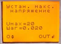
Valcoder set its maximum voltage (by the way it must be a multiple of 5 volts). Push OUT.
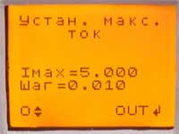
Valcoder set your maximum current. Push OUT.
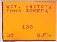
And that's where the desired frequency. Plug the parallel frequency ZQ1 and valcoder exhibit 1 kHz. Push OUT. Your setup is complete, and the PSU switch in the test mode.
Now a little about how to use BP and the modes
The voltage source can be changed 3 parameters. This output voltage, current limit/protection and defense mode.

All parameters are controlled by valcoder, switching between the settings button is used for U/I modes of protection exists 4: Limit - the current is limited to Imax, Imax Protection - the protection is triggered when exceeding Imax, Protection K. Z. - the protection is triggered only when exceeding the maximum current (Imax plays no role), there is No protection! - protection is disabled at all, but be careful with this mode, if a short circuit can be damaged! This mode is implemented for those cases where the tested device with a presence peak excess current consumption (for example ULF, subwoofer, etc.). Yes, the OUT button controls output power to terminals, to indicate the state of output voltage is possible by readings of the ammeter (if there dashes then the output is disabled if the value in figures, the voltage applied to terminals). When protection short audible beep that would re-submit the voltage at the terminals of the tap OUT.
When you click on VIEW PD is transferred to the graphic display of current consumption in the form of waveforms. The selected protection mode and voltage is maintained.
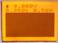
In this mode, you can control the output voltage and the parameter "time/div", value in seconds that indicates the sweep of the entire width of the display. To the right of the parameter "time/div" parameter is "amps/division", it cannot be set, it is automatically installed from minimum to maximum depending on current maximum current consumption. This value shows the entire height of the graph vertically, that is, the top graph is the value specified in amperes. What would it reset to the minimum you need to double press VIEW to switch to normal mode and back.
In BP implemented a charger that charges the batteries with constant current. For mode battery charge, press the MODE button, but the output voltage has to be switched off, otherwise the transition is blocked (made as protection against accidental pressing in during operation).
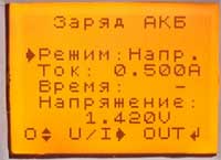
And so the charger has 2 modes: Voltage - charges up to a specified voltage with the specified maximum current at the specified voltage and current drop charge 4 times the charge is completed, the mode Time - all exactly the same, but the charge current attention is not drawn, and the charge is terminated after the specified time. The time is set in minutes. The start button is OUT, upon completion of a charging device emits a long sound signal and displays a message about the end of the charge. To interrupt the charge process at any time by pressing any button.
That's all. I think, told in some detail. Questions can be sent by e-mail: This email address is being protected from spambots. You must have JavaScript enabled to view it. or on ICQ: 330898528.
P.S. Perhaps you feel that the device is something missing or something not properly made (for example it is advisable to use more multi-bit ADC and DAC, etc.). But understand, I wanted to make a device primarily as a cheaper and easier. But in any case, waiting for comments and suggestions, where do without them. And applied the graphic display with the intention that would have been possible to make the display "waveforms", it is often useful in the repair of such complex devices such as cell phones…
Download the firmware and charge LAY in the format
Author: Alexey Chernov; Publication: www.cxem.net