


")

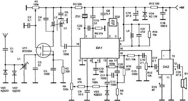
Figure 23. Receiver frequency deviation of 2.5 kHz.
The receiver is made by the superhet circuit on an integrated circuit KHA, which is designed to run in the path of the if receiver with double frequency conversion. To simplify the circuit in our case we use only one frequency conversion. The signal from the antenna is delivered to the input circuit L1, C3, tuned to a frequency of the input signal. Diodes VD1, VD2 serve to limit the input signal of large amplitude, for example, impulse noise. The circuit L1, C3 is fully connected to the gate of the transistor VT1 type KPA. This transistor performs the role of the resonant high-frequency amplifier. In the stock circuit a circuit L2, C4, also tuned to the frequency of the received signal. With the coil L3 communications the amplified signal is input to the mixer chip DA1. To the second gate of the transistor receives voltage VT1, remove from engine tuning resistor R1. By changing the voltage on the second gate of the transistor changing the gain of the resonant amplifier transistor VT1 and, consequently, increase the sensitivity of receiver in General. The heterodyne receiver is made on the elements that are part of the chip DА1, its frequency is determined is connected to pin 1 quartz resonator. The frequency of the crystal must be different from the frequency of the input signal at 465 kHz (in either direction). The output of the mixer, the if signal through the buffer cascade is supplied to piezoceramic filter ZQ2, which determines the selectivity adjacent channel. Output of the filter ZQ2 signal fed to the amplifier-limiter frequency converters and frequency detector included in the chip DА1. Patiekalai the HRC has a conversion gain of voltage of about 100. The detector is made in a double balanced multiplier. For normal operation of the detector necessary phase-shifting circuit L4, C21. Resistor R14 shunt circuit thereby extending the bandwidth. It determines the sensitivity and the noise level at the output of the device. The resistor R14 is selected according to the optimal value of the given indicators. Proyektirovanii the signal is amplified prior USC that is also in the chip DA1, is supplied to the volume control, performed on the resistor R12, a with this engine variable resistor - input USC made on the chip DA2 type CHA. The receiver has a noiseless system settings, which works as follows. When the input signal or the significant reduction of its level at pin 10 of the chip DA1 dramatically increases the level of noise that have the maximum spectral density in the range of 7-10 kHz. This noise is input to the active filter, assembled at the operational amplifier, which is part of a chip of DA1. The amplified noise signal arrives at the detector collected the diode VD3, where it is converted to a DC level. This voltage is fed to the input of the trigger, which is part of a chip of DA1, the output of which (pin 16), when no useful signal is set to zero. This level bypasses the volume control R13 and blocks the entrance USC. The threshold system is noiseless setting is set by the resistor R4. In the receiver chips instead of DA1 type CHA you can use the chip CPHA. This chip has a composition similar CHA, but has a different Pinout. Chips instead of DA2 can be used CAN, CAN or perform USC discrete. Transistor QP can be replaced by CP. Piezoceramic filter ZQ2-any small filter at 465 kHz. Coils L1, L2, L3 are wound on a cylindrical frame with a diameter of 5 mm trimmer with cores made of ferrite brand N, length 12 mm and diameter of 2.8 mm. Coil L1 contains 9 turns with a branch from the third coil, L2 - 9 coils, L3 - 3 turns of wire ELV of 0.3 mm. Coil L3 is wound on top of the coil L2. Coil L4 is wound on the frame from the inverter circuit broadcast receiver and contains 90 turns of wire sew 0.12 mm. installation perform the traditional way. Resistor R1 sets the maximum sensitivity, and resistor R4 - threshold noiseless settings.