


")

The 144 MHz transmitter is depicted in figure 1 works as follows. The audio signal from the microphone connected to the connector X1 is supplied to the microphone amplifier which is made on operational amplifiers (op-amp) A1. Resistor R7 to adjust the gain of op amp.
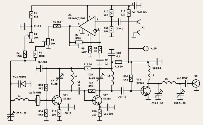 figure 1
The amplified signal from the output of op-amp is fed to the varicap VD1 to modulate the transmitter. Trimmer resistor R5 sets the optimal modulation mode. The master oscillator of the transmitter is performed on the transistor VT1. The oscillation frequency is determined by a quartz resonator Q1. By means of the variable resistor R3, the carrier frequency of the transmitter can be changed within narrow limits. The generator operates at the third harmonic of the quartz 145 MHz. On the VT2 transistor pre-amplifier assembled. The output stage of the transmitter are made on the VT3 transistor. The amplified signal of the transmitter is fed to the antenna through a matching P-loop is executed on the elements C15, L5, C16.
Coil transmitter of frameless Nakatani mandrel with a diameter of 5 mm. Coil L1 is 6 turns, L2,L3 - round 4, L4 - 10 turns, L5 - 5 turns. All coils are wound silver plated wire with a diameter of 1 mm. the Transmitter is located in the case of the 4 sections. Each cascade of the transmitter (microphone amplifier, oscillator, pre-amplifier, the output stage) is executed in its own section.
Establishing the transmitter to start with verify the correctness of installation. To the antenna output of the transmitter x2 connect a dummy. Measuring the RF voltage across the dummy adjust the contours of the transmitter signals at the maximum. The circuits L2, C7 and L3, C10 tuned to the third harmonic of the quartz 145 MHz. The establishment of a microphone preamplifier is to install the koefitsientom gain R7 and modulation mode R8.