


")

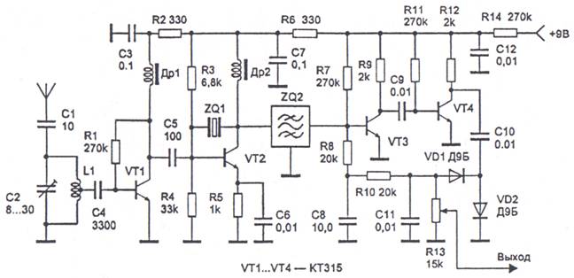
Figure 20. Radio with fixed frequency setting.
Schematic diagram of the radio receiver shown in figure 20. The received signal is allocated circuit L1, C2 and amplified by an amplifier of high frequency, performed on the transistor VT1. On the VT2 transistor is performed, the frequency Converter combined with a local oscillator and a quartz frequency stabilization of local oscillators quartz ZQ. The amplified signal from the collector of VT1 is mixed with the lo signal. As a result the collector of the transistor VT2 is formed, the intermediate frequency signal. The if signal is allocated piezoelectric filter ZQ2 with a frequency of 465 kHz and amplified by two-stage intermediate frequency amplifier, assembled on transistors VT3, VT4. The detector of the receiver is on the diodes VD1, VD2. From the detector signal is supplied to the AGC system, consisting of goals R8, C8, R10, and through the volume control R13 to the audio frequency amplifier. Diodes VD1, VD2 can be type D18, GD. Piezoceramic filter ZQ2 can be any of the tuning frequency of 465 kHz. Chokes DR1, dr2 do wound resistors MLT-0.25 a resistance greater than 100 ohms. Everyone has 100 turns of wire sew 0,1. The design of the coil L1 is similar to the previous description: it consists of 13 turns of wire sew 0.23 with a branch from the 3rd round. Setting begin with installation of currents of the collectors of transistors VT1-VT4. The collector current of VT1 (0.6 mA) is set by selecting the resistance of resistor R1. Currents collectors VT2-VT4 are set by the selection of resistors R3, R7, R11, respectively, equal to 1, 0.5 and 0.05 mA.