


")

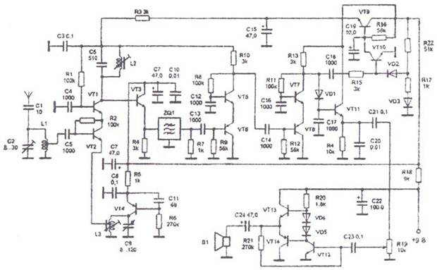
Figure 18. Radio receiver amplitude-modulated (AM) signals.
Schematic diagram of the radio receiver shown in figure 18. With antenna signal fed to the input circuit L1, C2, allocating bandwidth of the received signal. Selected high-frequency signal from the tap of the coil L1 is supplied to the base of transistor VT2, which is part of the cascade mixer. The emitter of this same transistor with drain coil L3 receives the lo signal, which is assembled on the transistor VT4. The frequency of the lo signal is settable customizados circuit L3, C9. The restructuring of the local oscillator is a variable capacitor C9. The frequency of the local oscillator must be different from the frequency of the received signal by the value of intermediate frequency, in this case at 465 kHz. Cascade mixer, collected on transistors VT1 and VT2, is the scheme of MA-ON. Thanks to this mixer has a large output impedance, which allows you to enable the circuit L2, C6, tuned to an intermediate frequency in the collector circuit of the transistor VT1. The modes of the transistors of the mixer DC current determined by the resistance of resistors R1 and R2. The output of the mixer, the intermediate frequency signal is input to the emitter follower, which is assembled on the transistor VТ3. He coordinates the high output impedance of the mixer with a low input impedance of the piezoelectric filter ZQ1. Filter ZQ1 determines the selectivity adjacent channel. It with a matched load, the function which performs the resistor R7. C the load and a voltage intermediate frequency (if) is input to a two-stage if amplifier, transistors VT5-VT8. In cascaded amplifiers are circuits based on transistors of different structure can be included under the scheme OK-ABOUT. The mode of operation of the transistors is determined by the resistance of the resistors R8, R9 and R11, R12.
The detector of the receiver made the diode VD1, which is loaded on a high input impedance emitter follower transistor VT11. The constant component of the base voltage of the transistor shifts the operating point of the diode VD1 in the forward direction and support her in the beginning of the curved section of the I-V curve that provides the best detection of weak signals, and therefore a higher sensitivity than the conventional detector. With load emitter follower VT11 proyektirovanii low-frequency signal is supplied to the volume control is performed on the resistor R19 and to the audio frequency amplifier. The receiver has an effective system for the automatic gain control (LRU). For the operation of the AGC system is used, the voltage of the inverter, remove from the collector of the transistor VT7. The positive wave of the voltage coming into the circuit of the base of the transistor VT10, when the level of the input signal, and thus of the if signal, opens. This leads to the closure of the transistor VT9, thereby reducing the voltage at the emitter of this transistor while decreasing the voltage of the mixer and the first stage of the HRC, which reduces the gain of these stages. The circuit consisting of R17 and VD3, is used to create the anode positive voltage VD2 shifting the operating point of the transistor VT10 in the direction of greatest sensitivity, thereby compensating for the attenuation introduced by the resistor R15. The audio frequency amplifier of the receiver is performed according to the standard scheme on the transistor VT12-VT14 and has no peculiar features. The load of the amplifier is a compact loudspeaker B1 with a coil resistance of at least 8 0m or head phones. The radio used type resistors MLT-0.125, electrolytic capacitor type K50-6, K50-16 or K50-35, trimmer capacitors tyre PDA, capacitor C9 is desirable to use air-dielectric, piezoelectric filter ZQ1 type FSP-061-08 or FPP-026 with a frequency of 465 kHz.
For winding coils used polystyrene frames rigged with cores made of ferrite NN diameter of 2.8 mm and a length of 14 mm. Coils L1 and L3 have 20 turns of wire sew 0.18 mm. the tap of the coil L1 is made from 7-turns, starting from a grounded output. The coil L3 withdrawal is made from the 1st round. The coil circuit of the inverter L2 is wound on a standard four-section frame and is placed in a tubular ferrite magnetic core of ferrite brand with permeability of 400, the core of the same material. Coil L2, contains 120 turns of wire sew 0.12 mm.
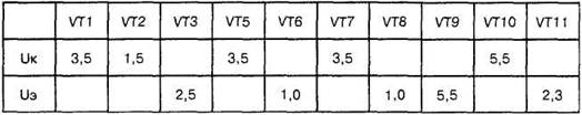
Installation should start from the amplifier of sound frequency. The selection of the resistance of the resistor R21 is set to the voltage in the connection point of the emitter of transistor VT13, VT14. It should be half the voltage of the power supply. The voltage on the electrodes of the transistors of the stages if and AGC is set by the selection of resistors in the base circuit when the input signal and disabled the oscillator. The required voltage value in volts is shown in the table.
Table voltage value at the terminals of the transistors
The circuit L2, C6 tuned to the frequency FC - 465 kHz. An input circuit configured to accept middle of the range. The radio can be used with transmitters having a quartz frequency stabilization. For this purpose use a range of fixed settings. This is achieved by changing the heterodyne scheme (figure 19).
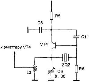
Figure 19. The use of a quartz resonator in the circuit of the heterodyne receiver.
Instead of a variable capacitor C9 is set trimmer capacitor. Quartz resonator ZQ2 included between collector and base of the transistor VT4. The frequency of the quartz ZQ2 must be different from the transmitter frequency by the value of the inverter equal to 465 kHz. When using multiple kartsovnik transmitters in the heterodyne receiver, you must use the appropriate number of quartz resonators, which are connected via switch.