


")

Diagram of the transmitter shown in Fig. 4. The device comprises a minimum of parts and is powered by batteries for electronic clock voltage of 1.5 V. With such a small voltage and consumed current of 2-3 mA signal from that wireless microphones may be taken at a distance of 150 m. the Duration of about 24 h. the master oscillator is assembled on the transistor VT1 type KT368, for which the DC is set by resistor R1. The oscillation frequency is set by the circuit in the base circuit of the transistor VT1. This circuit includes a coil L1, the capacitor C3 and the capacitance in the circuit, the base-emitter of the transistor VT1 in the collector circuit of which the load included a circuit consisting of a coil L2 and capacitors C6, C7. The capacitor C5 is included in the feedback loop and allows you to adjust the level of excitation of the generator. In oscillators of this type of frequency modulation is performed by changing the potentials of the findings of the generating element. In our case the control voltage is applied to the base of transistor VT1, thus changing the bias voltage on the junction, the base-emitter and, as a consequence, by varying the junction capacitance base-emitter. The change of this capacitance leads to a change in resonant frequency of the resonant circuit, which leads to the appearance of frequency modulation. When using УSW receiver imported the required value of the maximum deviation of the carrier frequency is 75 kHz (for domestic standard - 50 kHz) and is obtained by changing the voltage of audio frequency at the base of the transistor in the range of 10-100 mV. This is why this design is not used for modulation of the audio frequency amplifier. When using an electret microphone with amplifier, for example, FEM-3, M1-B2 "Pine", the signal level taken straight from the microphone output was sufficient to obtain the desired frequency deviation of the radio microphone. Capacitor C1 provides filtering of high frequencies. Capacitor C7 can slightly change the value of the carrier frequency. The signal in the antenna is fed via a capacitor C8, which has a capacity of specially chosen small to reduce the influence of disturbing factors on the frequency of the oscillation generator. Antenna made of wire or metal rod with a length of 60-100 cm Length of the antenna can be reduced if between it and the capacitor C8, to include an extension coil L3 (in Fig. 4 not shown). Coil wireless microphones frameless, with a diameter of 2.5 mm, is wound round. The coil L1 has 8 coils, the coil L2 is - 6 turns, the coil L3 is 15 turns of wire sew 0,3. When you configure a device to achieve maximum high frequency signal by changing the inductance coils L1 and L2. The selection of the capacitor C7 can slightly change the magnitude of the carrier frequency, in some cases it can be excluded.
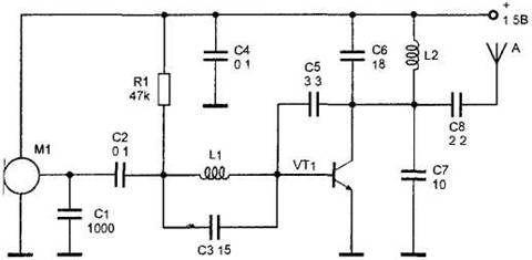
Fig. 4. The radio transmitter with a battery of 1.5 V.