Among the large family of transmitters can select those devices that have a simple circuit design, the small number of parts and thus have a relatively good characteristics.
The scheme is simple the microtransmitter is depicted in Fig. 1. The basis of this device is
the scheme of the high-frequency, oscillator tunnel diode. The current consumed by the generator from the power source, is approximately 15 mA and depends on the type of tunnel diode. The type of tunnel diode can be selected at the discretion of the ham, with a current of 10-15 mA (e.g., diode AIA). The generator operates at a voltage of power source 1 and above at the respective operating point of the resistor R2. Choke DR1 is wound on resistor 0.25 wire sew 0.1 and contains 200-300 turns. The wire was off the resistor, it is periodically smeared with glue "Moment", BF-2 or others. The inductance of the inductor should be 100-200 mH, the reactor can be prefabricated. Coil resonant circuit and is made without a frame and has 7 turns of wire ELVs-1.0 mm. the Diameter of the coil of 8 mm, the winding length of 13 mm. of the Coil L2 as well as L1 - frameless wound wire sew 0.35 mm, 3 coils, coil diameter 2.5 mm, length of winding - 4 mm. Coil L2 is located inside the coil of an oscillatory circuit L1. Configuring of the transmitter is to install the operating point of the tunnel diode by rotating the engine tuning resistor R2 until a stable generation and tuning the oscillation frequency of the capacitor C4. The antenna is a segment of bonding wire in a length of about a quarter wavelength. The modulation depth can be changed by selecting the resistance of resistor R1. The signal of this transmitter can be received on a television receiver. To simplify the design of wireless microphones is possible when using small condenser microphones included directly in the high-frequency oscillating circuit of the generator.
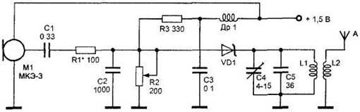
Fig. 1. The radio transmitter on the tunnel diode.
Possible
scheme of the transmitter is presented in Fig. 2. As you know, a condenser microphone is made in the form of a flattened capacitor with two flat fixed electrode, which is fixed parallel to the membrane (thin foil, metallized dielectric film, etc.), electrically insulated from the fixed electrodes. Protruding element circuit, a condenser microphone performs frequency modulation. In other respects
the description of the scheme and configuration of the transmitter is similar to the scheme above. The radiation power of the above devices is the proportion of units of mW. Accordingly, the range of these devices is unit - tens of meters.
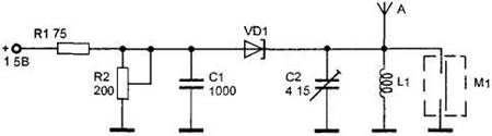
Fig. 2. Compact condenser microphone.


")
