


")

We continue the topic of the protection of home phones from the "pirates". The proposed the device is designed to protect telephone radiologicaly SANYO model CLT-55KM. Possible operation of such unit, together with other telephones with technical characteristics similar to the above model.
The product blocks the connection of the base unit (hereafter BB) to the telephone line to until the keyboard of the tube will not be dialed a four-digit code. Except also, are protected from BB "hangs", which can often occur when attempts pirate connection. If within 30 s after removal of the tube the correct code will not be dialed, the device will restart" BB. After successful the set of codeword occurs BB connection to a telephone line and the tube has a regular dial tone - dial tone PBX, offering start dialing from. To indicate the connection to the telephone line is led HL3 green on-Board device. After finishing the conversation and press The "END" of the tube, the device enters the normal mode, erase typed code and disables BB from the telephone line.
When incoming call, your device automatically connects to BB telephone line for the duration of the ringing signal. On an incoming the call is indicated by an led HL2 yellow glow. After clicking on press the "TEL" BB remains connected to the line to finish the conversation without a preliminary set of code sequences. Thus, the work phone when an incoming call remains unchanged.
For more security key of "FLASH" (the reset line) is blocked. When you press this key, BB remains connected to the line, but not reset occurs in the receiver will hear the busy tone. On some lines lock keys FLASH may not work.
For ease of reference code sequence can be written in the memory handset and call it each time before you dial.
The circuit protection device shown in the figure. It is powered by AC the power of radio. The polarity of the phone line values are not has.
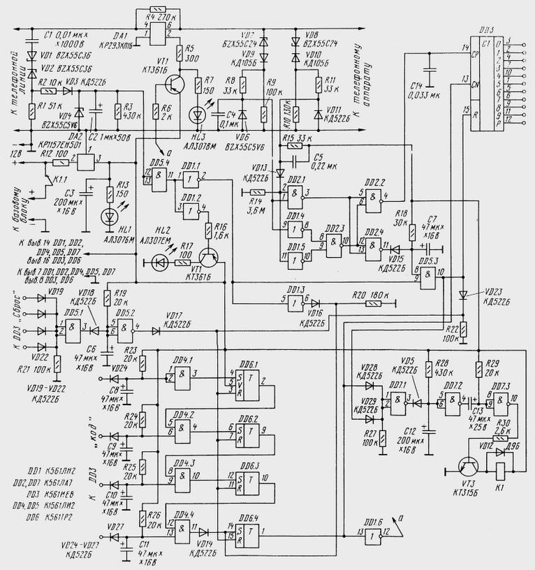
(click to enlarge)
Option code determines the jumpers between the outputs of the counter and diodes DD3 VD19-VD22 and VD24-VD27. After removal of the tube to the counting input of CP occurs DD3 low and when dialing or coded sequence of pulses, moreover, the number of pulses corresponds to the dialed digit. In standby mode on the output element DD5.3 should be high level, and when an incoming call or removed the tube is low.
The time constant of all integrators R23C8, R24C9, R25C10, R26C11 constant. They provide a signal delay of about 0.35 C. reset the counter on DD3 exit 0 there is a voltage of high level, and on all other outputs (1-9) there is a low voltage level. At each change of level on the CP input from low to high logical unit will be consistently to move from 0 to exit 9 and then again to 0, 1, 2. The integrator input item DD4.1 is responsible for the first digit in the sequence, DD4.2 - for the second, DD4.3 - the third and DD4.4 for the fourth.
Assume that the code sequence consists of numbers 4853. Then the diode VD24 must be connected to the output 4 of the counter DD3 (pin 10), the diode VD25 - to the exit 2 (pin 4), the diode VD26 to exit 7 (pin 6), and diode VD27 to output 0 (pin 3). Why this is so will be clear from the narrative. After picking up the handset a high level will be present at the output of counter 0 DD3 (pin 3). In typing the first digit is "4" high will shift to the output 4. Using 0.35 (during miseries pause) at the output of the element DD4.1 and the output of the trigger DD6.1 there is a high level, which will permit the passage of signal to the input of the trigger DD6.2. After dialing of the second digit ("8") at the counter DD3 received eight clock pulses and a high level will be present on output 2 (pin 4 of the chip DD3). After 0,35 with the output element DD4.2 appears a high level. Just entered and the remaining numbers.
If all digits are dialed correctly, the output of the trigger DD6.4 will arise high level, which would prohibit the operation of the counter DD3 and through the transistor VT1 will open optoelectronic key DA1. Thus the phone will be connected to line.
Diodes VD19-VT22 connect in a random order to free outputs counter DD3 with the condition that the two outputs DD3 connected to the system reset (DD5.1, DD5.2), must be either free access or exit connected to the input system code (DD4.1-DD4.4). So, if one of the diodes VD19-VD22 connected to the output 1, then it outputs 0 and 2 to connect the system reset it is impossible. In the case of the selected code sequence (4853) system reset you can connect, for example, the outputs 1, 3, 5, 8.
In standby mode the output element DD7.3 there is a low level, the relay K1 de-energized through the contacts K1.1, power is supplied to the base unit. If using 30 s after removal of the tube will not typed the correct code sequence, the output element DD7.3 there is a pulse of 1 s. the Relay K1 work, and nutrition BB will be interrupted.
Mounting the unit begins with a circuit (R12, DA2, NW, R13, HL1). Connecting external power adapter with adjustable output voltage change the supply voltage is in the range of 10 to 14 V. at the same time control the voltage at the input and output of the stabilizer DA2. At the entrance it has to change in the range of 8 to 12, and the output is to be permanent (5 In).
Next, assemble and customize the control unit and control line. Set the sensor elements of the incoming call (C1, VD1, VD2, R1, R2, VD3, VD4, C2, R3) and the resistor R4. Then mount the sensor set, assembled on the elements VD6-VD11, R8-R11, C4, C5, R15. The unit is connected to a telephone line (positive output line to the upper circuit point) and check the voltage on the capacitor C2. In standby mode (line 60) must be equal to zero, and when exposed to ringing - 3,5 5,6…V.
Then connected to the output of the phone (BB) and in standby mode check the voltage the Zener diode VD6 and VD11, first when you hang up, and then when raised. When lowered the tube voltage VD6 should be 5.6 In, and when hanging up on VD6 must be zero. The diode VD11 in both cases to be supplied with voltage of 5 V.
After that change the polarity of the telephone line and check again the voltage on the capacitor C2 on the methodology described above. In standby mode for hang up on VD6 VD11 and should be a voltage of about zero, and when raised: VD6 - zero, and VD11 - 5 V.
Zener diodes VD1, VD2, you can apply type SA, VD4 - XA, VD7 and VD8 - SA, XG, XG.
Author: A. Novikov