With a shortage of telephone lines sometimes apply a high-frequency apparatus seal (AVA). Unlike the lock that disables one of subscribers from the line while she takes another, AVA provides the opportunity for two the subscribers to use the one line simultaneously and independently from each other. The proposed device allows you to connect to such modern lines telephones with push-button dialing, Fax machines, caller ID.
Using the system of the AVE line telephone (SLT) one of the subscribers the usual way connected to the line, and its owner, as a rule, does not know about the existence of the second channel, which is implemented at the expense of frequency seal. In the room where the second subscriber, is a block RF A. while on phone the station of this line is connected to the unit RF-P signals from the second subscriber device transmitted at a carrier frequency of 28 kHz with the use of amplitude modulation (AM), and the signals of the station is at a frequency of 64 kHz. Block HF And connected to a line through an isolation transformer. To power it uses a network of 220 V. The possibility of connecting to the terminals "+B" and "B" battery backup of eight electrochemical cells 373.
Block HF-A. which was developed for devices with mechanical the dialer has at least two significant drawbacks: low output voltage (10 V) and the need for three-wire connection THAT (L1 - signaling, L2 - General, SG - separate conclusion of the call). Because of this experience various problems. The fact is that THE modern electronic dialer as a rule, do not have a separate output call. Often they can't work with the line voltage 10 V (standard domestic lines - 60 In, for foreign - 45). As a result, the connection of two or more THE unit is very difficult. In addition, full-time job TA today. cordless phones and such now common devices like modems, the faxes. Caller ID, answering machines, etc., is impossible.
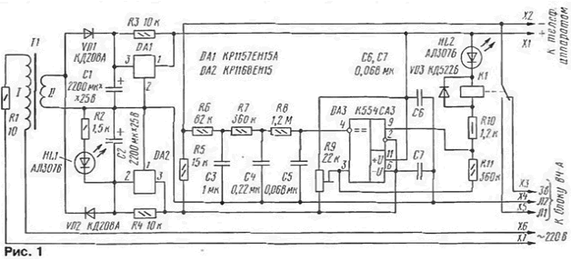
To eliminate these drawbacks and limitations, without interfering with standard the equipment will help the adapter, the scheme of which is shown in Fig. 1. The main nodes this device is stable bipolar power supply of ±15 V. passive low-pass filter, Schmitt trigger with a powerful output and actuating relay. Green HL1 led is designed to indicate the enabled state of the adapter, and red illuminates when HL2 is removed, the tube or when THE line is any another device.

If the tube is laid on THE lever, to the inverting input of the comparator through DA3 resistors R5 - R8 receives voltage -15 V (referenced to GND, which is conventionally adopted contact connector X4). This voltage is below the threshold actuation installed trimming resistor R9 to the noninverting input of DA3. therefore, the output transistor of the comparator is closed, the indicator HL2 is not lit, relay K1 is de-energized. THE one connected to the bell output of the block HF And through the contacts relays and ready to receive the call signal.
When hook through spoken node of THE constant current flows. Resistance conversational node is approximately an order of magnitude less resistance resistor R5. As a result, the voltage on the inverting input of the comparator changes the positive polarity, the output transistor of the comparator opens, the led turns on HL2. relay K1 is activated. Their contacts relay disables from THE bell output and it connects to the signal output unit RF-A. This is mode classes hotline to dial the number, to talk, to share data by Fax or modem.
Thus, three-wire line unit RF And converted to standard two-wire, which, as usual, you can connect one or more of THE one or the other devices. The order of the signals is the same. as in the lines without AVA.
In the mode line classes block HF And its power source and one of stable sources of adapter is connected to THE successively. Therefore, the line voltage for TA = 25 V. the Practice has shown, this information is sufficient to complete the work as different TA and the devices listed above. Such low voltage and low voltage ringing signal (about 50) allows you to safely apply any import THE one with no special adaptation to local telephone networks.
LPF R6C3R7C4R8C5 dozens of times weakens the pulse dialing and ringing of the signal. This is necessary to standby ringer does not lead to the actuation of the relay, and in the mode of occupation of the line pulse dialing does not lead to his release. Trimmer resistor R9 allows you to set such a threshold positives, which will provide a clear separation of these two States. Positive feedback through the resistor R11. converts the comparator in DA3 the Schmitt trigger. reduces its sensitivity to fluctuations of the output voltage The low-pass filter, preventing false alarms.
Resistors R3 and R4 are designed for the safe launch stabilizers (as a rule, they are not needed when using imported chips).
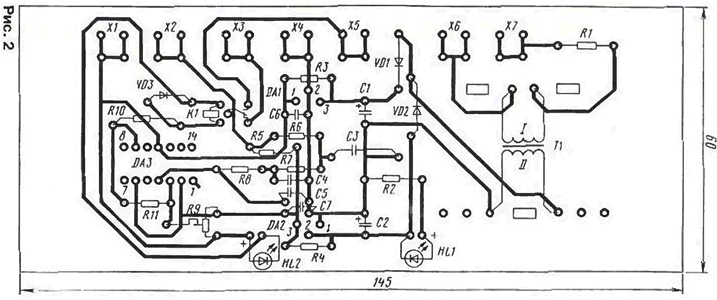
The printed circuit Board of the adapter depicted in Fig. 2. It is made of unilateral foiled fiberglass 1.5 mm Secondary winding of the transformer T1 must provide a voltage of 15 V at a current of 0.3 A. Relay K1 - RES-15. passport RS4.591.004. You can replace the relay of the same type with passport RS4.591.001. but instead of the resistor R10 must be set the jumper.

When the adapter Assembly note that the chip stabilizers Dating various cocoliche. The import analogues of these chips (78L15 - DA1 and 79L15 - DA2) pinouts correspond to those shown in Fig. 1.
Resistor R9 - SDR-386. the rest - ML T. the Capacitors C50-35. Km and K73-17. All resistors and capacitors can have a deviation from the nominal value within ±20 %.
Wireless adapter card is placed in any suitable size enclosure, come close to block RF A. the Total length of the wires connecting the block with the adapter and the adapter THAT should not exceed 25 m.
Configure the adapter in two stages. First, please make sure it is working. Connecting the power, check the voltage at the inputs and outputs of the stabilizers. Then, with engine tuning resistor R9 to the middle position, close contacts X1 and x2. Then the relay must operate, and the led HL2 - glow.
In the second stage settings choose the threshold. The adapter is connected to the RF unit and connect THE same. First perform a rough selection. If the led HL2 does not light up when removing the tube, turn the engine counterclockwise R9 arrow (down) until HL2 will not start reliably ignite (relay makes a little click). If the led HL2 goes out when lowering the tube the lever THAT turns the engine R9 clockwise (upward in the diagram), while HL2 starts to fade after about 0.5 s after lowering the tube (with relay also makes a little click).
Then produce the exact choice of threshold. If you do not gain such digits 8, 9, 0, and the tube then there is a beep, turn the engine R9 counterclockwise, checking the reliability of a set of numbers "0" . If the led HL2 lights up during a call and the relay clicks, the engine R9 slightly turn on a clockwise direction until the effect disappears.
Author: A. Brazhnikov, Penza


