


")

The proposed device is characterized by simplicity and cheapness. However, with his we can check and repair telephones, using a complex cases oscilloscope.
Diagram of the device shown in the figure. It consists of the following nodes: node call, the node control dial, the node power. Call site consists of capacitor C3, resistor R5, buttons SB1 (without fixation) and normally closed contacts K1.1 relay. In the node control dial includes relay K1, a Zener diode VD3, VD2 diode, LEDs HL1, HL2, resistors R1-R4, the transistor VT1. Led HL2 controls the opening line when dialing a HL1 - circuit. Node supply consists of a power transformer T1, a diode bridge VD1 and the capacitor C1.
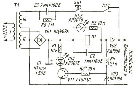
While on-hook telephone (hereafter TA), its resistance DC is great, the relay K1 is not activated, the led HL2 is not lit, a HL1 - lit. When the closure button SB1, the AC voltage from the winding III is fed to TA. Calling device operable SHE must submit the sound of the call. The Capacitor C3 need to limit ringing current, and the resistor R5 to discharge this the capacitor.
The node control dial works as follows. Hanging up THE its resistance decreases sharply, the relay K1 is activated, the led is switched HL2, normally closed contacts of relay K1.1 opens and submission call the signal THAT will be banned. HL1 led will continue to Shine, as the output voltage of the device will be installed within 8… 15 V, and enough to open the transistor VT1. In a telephone earpiece THAT will be heard the background frequency of 100 Hz, which eliminates the need for additional sound generator frequency to check the telephone earpiece tube.
When dialing LEDs HL1 and HL2 should be flashing. During pulse dialing rooms THAT periodically closes and opens the telephone line. When opening HL2 goes out, when the circuit turns off HL1. The resistor R3 is chosen so that HL1 led was extinguished when closed the output terminals and shone in all other cases.
To test your microphone must be connected to the output terminals of the oscilloscope with closed the entrance. Pronouncing different words in a tube THAT, test the microphone with an oscilloscope. However, .practice shows that such a failure e-THAT is rare.
For the device will fit any low-power mains transformer with a voltage winding II 25…30 V at a current of 50…100 mA and the voltage across winding III 50 70 In… at a current of 50… 100 mA. Thus, the output voltage of the device when on-hook telephone set (or its absence) should be about 40 V.
The capacitor C1 is any oxide. To use a capacitor with a larger capacity than indicated in the diagram, is undesirable, since this will reduce the ripple, but they are necessary to check the telephone earpiece. Capacitors C2 and C3 is non-polar, for example, MBM. Relay K1 - RES (passport 131) winding resistance 750 Ω or more with operating voltage 22…30 V operating current 20…35 mA. Diode bridge VD1 - any for a voltage less than 50 V and a current of 100 mA. The Zener diode VD3 can be replaced by KS147A. Diode VD2 must withstand a reverse voltage of 100 V and a direct current is not less than 50 mA. Transistor CTD can be replaced by CTE.
When establishing the unit needs to pick up the resistor R3 so that the led HL1 reliably extinguished when closed the output terminals and glowed, when they connect the two series-connected silicon diode (anode to VD2).
Author: K. Movsum-Zade, Tyumen