


")

In Fig.1 shows a diagram of a simple indicator the line was busy. It is intended for the apartment where the rooms are equipped with several parallel-connected ONE, and allows the LEDs to determine that one of the devices is a conversation or not lies with the destination handset. Unlike the similar purpose schemes, published in [L1 p. 140] and [L p. 46], it is in standby mode from the line consumes less current with a smaller number of parts.
The indicator is based on using the properties of the transistor VT1 when in micro mode to provide high gain. And since it is included without negative feedback, it is possible to switch from saturation in the closed state requires a small change in the voltage on the collector. When the operation of the circuit in the initial state, when in the TL 60 operates In, the transistor will be in saturation, i.e. at the gate VT2 will not stress. Once the pipe is removed from the machine - line voltage drops to 6…15 V, which leads to the locking of the transistor VT1 and VT2 with the shutter divider formed by resistors R1-R2 and R3-R4, a voltage is applied. Its level is sufficient for opening VT2. .
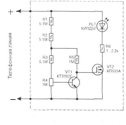
Fig. 1. Scheme
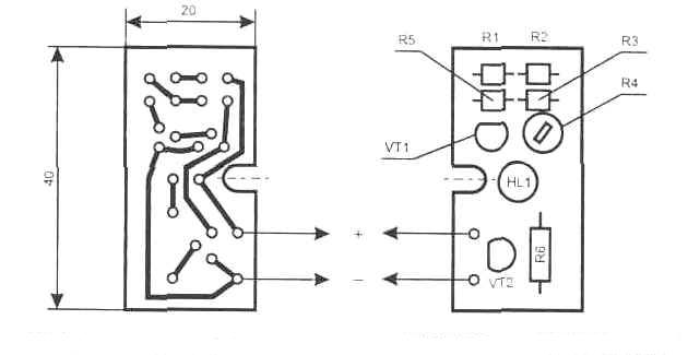
Fig. 2. Printed circuit Board
Configurable scheme-built resistor R4 (SDR-19a) so that the led HL1 had ceased to glow at a voltage of 16 V. the Interval led a total of 6.4…15 V, which corresponds to the removed tube. For assembling the elements of a printed circuit Board is shown in figure 2. It fits easily into a standard phone Jack or inside THE same.
Publication: www.cxem.net