


")

The proposed device will allow ATS to check and configure different nodes of switching equipment, subscriber units, means automatics. It contains a handset with advanced features, tonal answering machine, signal generator, frequency counter.
The device is intended for use primarily by service personnel automatic telephone stations (ATS). The purpose of its creation was to unite in one device, the number of necessary devices and thereby replace personal the tube, which have each electrician, electrician, and sometimes I engineer.
The main functions of the phone:
- decoding signals the PBX;
- displaying information on the display;
- automatic dozarivanie when hook with TA;
- automatic dozarivanie clicking on one button;
- automatic dozarivanie timer;
- automatic dozarivanie at last entered the room;
- memory 5+1 rooms (up to 15 characters each);
- audible confirmation of button presses;
- the consideration of the duration of the call;
- clock;
- the alarm clock.
The device allows people to talk to, output to the subscriber line, and separate output audio signals, to measure the interference signals automatic stations to measure the signal frequency as a frequency counter. Today perform these measurements are used, the frequency, the low frequency generators signal oscilloscopes etc But in some cases such use is questionable for a number of reasons.
First, it is difficult to drive around the neighborhood frequency counter or oscilloscope, if they even the most modern (size allows it to do). Even if you know that you need me, shaking on Russian roads - not the best conditions for the measuring instrument of this class. Secondly, it makes no sense to measure values with high accuracy (at least always) with the norm the parameters have wide tolerances. For example, the signal "Response station has a frequency 425 Hz, and the tolerance range is ±25 Hz for some exchanges. Why measure this signal with precision 425,05 Hz, for example, the frequency 43-34, if its value is allowed in the range from 400 to 450 Hz? As a result, in practice, many parameters are not measure at all.
When you search for pairs in the cable can be used another person with the appliance or special tester with the LF generator, homemade generator low cut, certified the bass signal generator GZ-118. Using the proposed device will simplify the search procedure, and in some cases it is simply irreplaceable. Neither one of these methods cannot be filed in the line under voltage station battery, low frequency signal without additional devices.
Using the proposed apparatus will accurately and quickly to measure some quantities, in some cases, not even leaving for the station and not resorting to expensive devices. I do not propose to abandon the use of certified measuring devices, I suggest that for highly specialized measurements use a specific device. As a result the wait staff will bring the device up to a maximum of 500 g instead of multiple devices weighing 5 kg or more each. The gain in weight and power consumption - dozens of times.
The linear part corresponds to the linear part of the apparatus of the first class. Tonal the answering machine works as follows: receives three signals make the call with the level of 15 to 150 V with a frequency of from 15 to 50 Hz and gives a line signal with a frequency of 700 Hz, the level of 0.5 at 600 Ohm load with a duration of 4 s. the low frequency Generator signal has a frequency range from 1 Hz to 500 Hz. The pulse duration and pause variable from 0.1 to 999 MS. The number of repetitions from 1 to 999 or indefinitely. The frequency measurement range of the signal "Response station" - from 350 to 500 Hz, and the signal "Call" is from 15 to 50 Hz.
Power supply - 220 V (external IP) or from the battery pack. Current. consumption - 25 mA (peak value - 100 mA).
Diagram of the device shown in the figure.
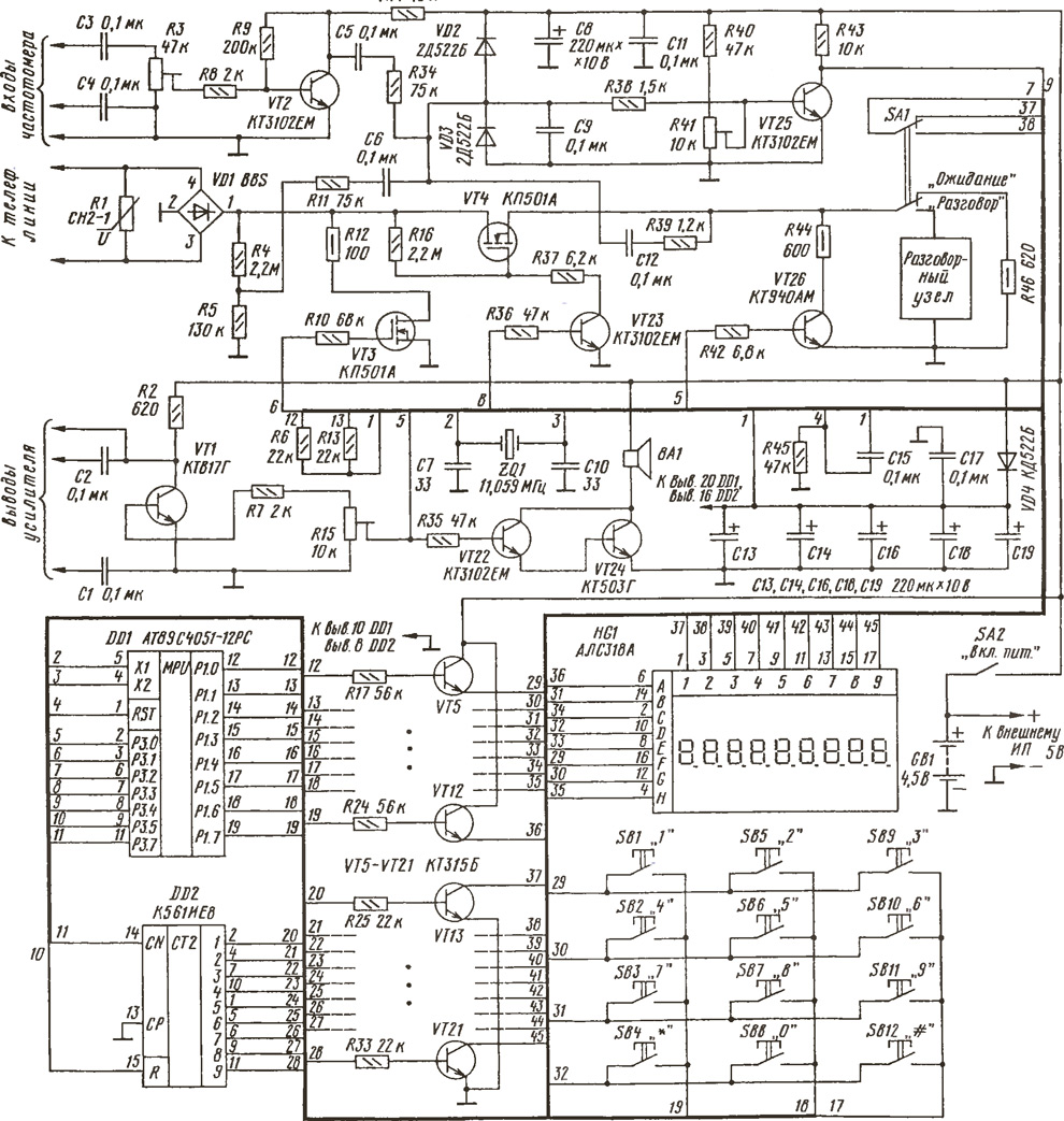
(click to enlarge)
The main element which controls the the entire device is a microcontroller with DD1. All information is displayed on the indicator HG1. The site of formation of the switching signal bits for dynamic the display is assembled on the counter and DD2 transistors VT13-VT21. Information on the indicator comes through the port P1 of the controller DD1 and transistors VT5-VT12. In the beginning of each cycle of the output image from the output of P3.5 DD1 comes a reset signal counter DD2.
A tone signal in the line and also the signal for the issuance of exit are formed on the output of the RZ.About controller DD1. Signal amplifier assembled in-line transistor VT26, and to issue to the output - transistor VT1. The above described signals, the signals audio confirmation of pressing buttons and a call signal is received through the chain of R35, VT22, VT24 on the dynamic head of BA1.
The signal circuit loop controller outputs a RZ.W, and the signal dialing - output P3.1.
Signal call from the subscriber line is supplied through a diode bridge on VD1 the resistive divider R4R5. The attenuated signal through the circuit R11C6R38 is input to amplifier transistor VT25, and with him - to the input of P3.4 controller DD1. The adjusted resistor R41 you can adjust the sensitivity of the amplifier. Diodes VD2 and VD3 protect the transistor VT25 from overloads.
Tone "Response station is removed from the subscriber line load - resistor R46 and through the chain R39C12 is supplied to the amplifier (transistor VT25).
The amplifier transistor VT2 is used to amplify the signal received at input in counter mode. Through a chain C5R34 this signal is input to amplifier transistor VT25.
Power to the controller DD1 and DD2 counter is fed through a filter consisting of a diode VD4 and capacitors C13, C14, C16-C19. Together these components significantly reduce throws voltage. A power disruption with mains unit for up to 1 does not interfere with device operation.
Spoken node used are standard from any phone. Lever switch switches SA1 subscriber line with a resistor R46 to spoken node.
Keyboard standard applied, 3x4, a total of 12 buttons. The signals from the buttons served in the controller DD1 to the port P1. During readout, the controller analyses the state of the buttons. If the button is pressed continuously, it is possible damping the corresponding segment on the display.
Now consider the establishment of units of the apparatus. Let's start with the fact that the first enable to produce without the controller DD1. The left circuit output resistor R10 should be connected to GND, and the output resistor R36 - to the positive the output of the power source. To the terminals of the telephone line in parallel connect a variable resistor of 3 kω power not less than 2 watts, putting it maximum resistance. To the collector of the transistor VT25 need connect the oscilloscope. Common wire of the oscilloscope must be connected to a common wire the device through capacitor of 0.47 µf with a working voltage not less than 250 V.
When connecting the power source, the total current consumption should be no more than 10 mA. Now the left output resistor R36 should be connected to GND, transistor VT23 closes a VT4 - opens. The device will load the telephone line. Turning the engine resistor R41, it is necessary to achieve the appearance of the signal "Response station" on the oscilloscope. Then to the line connect a millivoltmeter. Turning engine additional resistor, check the limits of sensitivity of the amplifier transistor VT25. Especially fond of sensitivity is not necessary, in real the work signal "Response station has a sufficient level. The Busy signals and "CPW" level signal exceeds the "Answer."
After configuring the amplifier transistor VT25 engine of the resistor R41 not to touch. Disconnect the voltmeter from the line, and then an additional resistor. To connect resistor R36 to the positive output of the power source. The device will disconnect the line.
To monitor the passage of ringing need to call from another phone on the custom. On the oscilloscope, you should see the pulses of the signal call. The sensitivity can be adjusted by selection of the resistors R4, R5, R11.
To check the signal in the line you have to connect the subscriber line instead the power source voltage 15…20 V, with a current capacity of 100 mA. Then submit with the LF signal generator frequency 2500 Hz with a level of not less than 2 In the left scheme the output resistor R35. In the dynamic head BA1, you should hear a sound. Submit on the left output resistor R36 low and to the terminals of the line to connect through the condenser headphones impedance of 300 Ohms. They should be heard the signal is. Its level should be about 0.5 V. If different from this value, choose the resistors R42 and R44.
Then you need to power off the device and install the microcontroller. To turn on the power. In the initial state, the apparatus displays on the indicator number rooms at the RAM, the current time with seconds "5_12-3345", queries the keyboard and subscriber line. In the absence of indication check for the signal frequency of 60 Hz at pin 9 of the controller DD1 signal and a frequency of 540 Hz at pin 11. If they are not, you need to turn off the power, unplug the above conclusions from the chains device (for example, by bending those pins) and again to check the presence of signals. If there are no impulses, test the operation of the master oscillator (the signal frequency 11,059 MHz at pin 4 DD1).
If the controller generates all the signals, and the display is still there, the reason may be the failure of a counter DD2. If no image is displayed in any discharge should check the appropriate resistors and transistors. The brightness of the indicator can be increased by resistors R17-R33 smaller resistance. This will lead to an increase in the total current consumption.
When the power needed to run the pre-install: install the current time, the response time of the timer, the timer mode and the room In RAM otherwise the device will begin to work with the initial settings. The watch will be to count the time from scratch. The timer is set to 25 hours and 25 minutes, i.e. never not exact timer with the current time. Rooms in RAM will be saved in the process.
To dial the number you need to dial the desired number. Pause between the first and second numbers should be no more than 2 s. "When you set the indicator displays the dialed digits. After you enter the fifth digit, the device will connect to the line and start dialing. Once the device starts counting time and the indicator will display "-TIMES-047-". Need for conversation toggle switch SA1 in the "Conversation". If this is not done, through 20 with the device will disconnect the line and returns to the initial state.
The output signal from the generator is always supplied in line outputted through the output amplifier can be heard in the dynamic head.
When you perform a wrong action the unit emits a long beep and gives an indicator of the "WRONG" (for example, if you do not set all the parameters for generator) and invites for further action: "-".
If after Autodialer not to switch the switch to "Talk", the apparatus 20 with after dialing will disconnect the line and go into the source state.
The device is an audible signal confirms button presses, and provides repeat pressing the button, if the button is pressed continuously. If you enter more than 9 digits information on the indicator moves to the left. On the display you can see the last 9 digits rooms.
Now consider in detail the instructions for use of the apparatus.
PREPARING THE UNIT FOR OPERATION
To turn on the power. The machine will beep. The indicator consistently shows "tA-21 001", "УCt HOURS" and the invitation to "-". Enter "44MMZZDDG", where HH is hours, MM is minutes, and ZZ is the number, DD is the month, G - year.
Press the "*". The display will show "-YCt Beads!-" and the invitation to Enter "AWEE" where AABB is the alarm time or run time automatic dozarivaniya, AA - clock, BB - minutes. If = 00, set the alarm, if = 02, installed automatically at a set dozarivanie time. Press "*". The display will show "УСt RAM-" the invitation "-". To enter in the RAM the first number from 1 to 15 characters. At this number the machine will set when removing the tube from the machine. Press the "*". The indicator will display"^ HH-MMSS". This is the initial state. K - number of rooms in RAM, HH - hours, MM - minutes, and SS is seconds. The clock shows the time. To enter in the second RAM room. This is a room in which the machine will automatically dozarivanie on a timer. The following rooms in the RAM can be omitted. They will be stored in RAM as you enter during operation. Before entering the last room in RAM to call a number from RAM is impossible.
AUTOMATIC DOZARIVANIE WHEN REMOVING THE TUBE FROM THE MACHINE
To remove the tube from the machine. You will be prompted "-". Within 2 to not gain the number on the keyboard. The device will RAM the first number on the indicator, will make pause 2 for the decision for further actions and execute dialing.
AUTOMATIC DOZARIVANIE A NUMBER IN THE RAM
Dialing from RAM. Typing the serial number (1-5), where is the desired number. On the display shows the dialed number. The device paused with 2 and display on indicator light the entire room. 2 apparatus connect to the line and begin to dial the number. During these 2 can be cancelled with the action button "*", otherwise the device will dial the called number. On completion of dialing, the display will show the message "-TIME-XXX", where XXX is the duration in seconds. For conversation need to transfer the switch to "Conversation" at any stage of the connection process, but not later than the 20th day after the completion of the dialing apparatus.
MAKING A CALL BY AN ARBITRARY NUMBER
Dial the desired number. After dialing 5th digits the machine starts to dial a number in line. When the recipient answers, the conversation translate switch on the unit to "Talk". After dialing in the indicator will display "-XXX". Time is counted from the moment the end of a set.
AUTOMATIC DOZARIVANIE BY LAST NUMBER
In the RAM of the device is stored last number that was showing the indicator to Cause it you can press "#". The machine will print the number on the indicator and will pause within 2 s. If you do not cancel the set button "*", the phone will dial the number.
VIEW ROOMS AT THE RAM
Typing the serial number of the RAM cell. The machine will display the number on the indicator. Before the expiration of the 2 press the "*".
SOFT RESET FOR THE CORRECTION OF THE CLOCK, CALENDAR AND NUMBERS IN RAM
Consistently on the keyboard to dial "*##3". The machine will reset, go at the beginning and will be given on the indicator "tA-21 001". You must perform all actions which were carried out in preparation for the work.
VIEW TIMER
Sequentially dial "*##5". The unit will beep and display on the indicator "t AA-BB.E", where AA - clock, BB - minute, E is 0 or 2. To reset readings press the "*", or 12 with the machine will go into the source state.
RESETTING THE TIMER MODE AND ROOMS IN RAM
Consistently typing "*##6". The unit will beep and will be given on the indicator "Set Bud" and the invitation to "-". To enter the time for the timer mode, then all the rooms in the RAM.
FREQUENCY MEASUREMENT
To connect the machine to the line. To measure the signal Response station" consistently typing "*##1". The device will connect to the line and will display "FF-Hhhhz", where XXX is the frequency of the signal "Response." The handset within 10 seconds will indicate the frequency of the signal. After that, he will issue a double beep will disconnect the line and returns to the initial state. When no signal is input, the device emits a double beep, gives message-HEt SIG-" and returns to initial state.
To measure the frequency of a signal to call" consistently on the keyboard dial "*##2". How to call from another phone in the room, which is connected to the handset. The display will show the message "PV - Hhgc" during the signal Sending call", where XX is the frequency of the received signal.
When measuring an arbitrary frequency, the device is not connected to the line. Submit the measured signal to the input frequency. To enable the counter operation one of the methods described above. To adjust the signal level of the resistor R3 to the indicator appeared testimony.
THE OUTPUT OF THE LOW-FREQUENCY SIGNAL ("GENERATOR")
Consistently typing "*#HHHOOOTTT##4", where XXX is the duration pause, WHOO - pulse duration in milliseconds, TTT - the number of repetitions sequence. If TTT = 000, number of repeats endlessly. The device connect to the line and give the dialed sequence. On completion of the unit gives message "ALL BЫd." and returns to initial state. To repeat typing "##4". After first pressing the "#" on the display it will show options.
For the issuance of tonal sequences subscriber must establish the connection in any way and put the switch to "Talk". To perform the actions described in the beginning of this section. After issuance of a sequence the device will disconnect the line itself. Since storage 6-th number in RAM and generator parameters are used the same cell, after entering the settings generator 6-th number in RAM disappears.
ANSWERING machine
When a call arrives, the phone beeps and displays the indicator "The CALL.", where X is the sequence number of the received call. After taking third parcel apparatus closes the loop, gives a line signal with a frequency of 700 Hz in 4 and, is disconnected from the line and returns to initial state. If desired need to talk to toggle the switch (to pick up). Work the answering machine is broken.
THE ALARM GOES OFF
The coincidence of the current time set in the timer apparatus emits an intermittent beep. You can turn it off by pressing any button, but in this case is added to the timer unit, i.e. a reset timer to a new time (set time + 1 minute). If you do not press button after one minute, the device will cease to sound intermittently signal. Implemented a way to attempt to stop the alarm got the name "runaway alarm clock". If awakening is trying to turn the alarm off "is not deliberately, the machine makes a reinstallation of the alarm clock to the new time - escapes one minute increments.
A CALL TIMER (REMOTE ALARM)
When matching the current time and timer, the apparatus displays a second indicator room and executes from RAM set on it. After dialing in-line displays audible alarm for 12 C, shuts down and goes into the original mode.
The firmware of the controller
Literature
Author: I. Chernev, Lipetsk