


")

If you want a wireless remote listening telephone calls on your telephone, you might want to try diagram miniature transmitter with frequency modulation, designed to work in the range УSW at frequencies of 63…80 MHz in conjunction with any residential receiver.
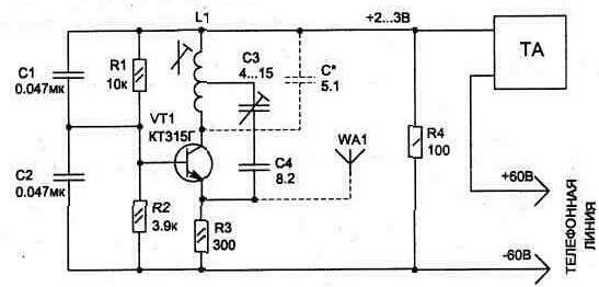
Fig.2.16
Diagram (Fig. 2.16) is powered by the telephone line only during the conversation, when raised handset.
Listening talk radio on the plot in the range where no broadcasting stations. The range of the transmitter without the use of antenna WA1 to 50 m, and to increase range, except for the use of the antenna, you must use a receiver with high the sensitivity. Thus, the increase in receiver sensitivity 2 times as much increases reception range.
When the device is connected to the telephone line must observe the polarity shown in the diagram.
Setting the scheme is in the restructuring of the generator the core of the coil L1 to the desired frequency УSW range, and then the capacitor NW it is necessary to adjust the transmitter, controlling the reception quality of the transmission to the hearing. Frequency modulation in the transmitter is obtained by changing the inner tank transistor when the voltage supply circuit by the current flow in line with the conversation.
Before configuring the transmitter must be connected it to a telephone line and removed when the tube is to measure the voltage across the resistor R4. It should be in the range from 2 to 3.5 V, and if the voltage is greater then you should reduce the resistance of this resistor.
The transmitter circuit is assembled on a one-sided printed the Board size 20 x 40 mm, to the pads which are soldered elements (see Fig. 2.17). Board size allows you to place it in the body of a standard telephone jacks.
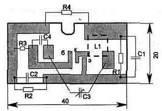
Fig. 2.17
The capacitor NW type KCM, and the rest used resistors and capacitors can be of any type, small-sized. Coil L1 is wound on the frame 5 mm diameter wire sew 0.23 mm and contains 5+5 turns. Transistor CTG can be replaced by CTA, and use other transistors it is not recommended, as this greatly increases the level of harmonics may cause interference in other bands. When indicated in the diagram detail level the second harmonic of the transmitter is less than 40…45 dB relative to the fundamental frequency.
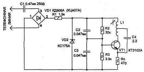
Fig. 2.18
As an antenna you can use a piece of any stranded wires 30, 40 see..
Tuning to the desired frequency, if there is no high frequency the ferrite core, it is possible to perform the selection of the capacitance of the circuit shown in the diagram by dotted lines. Capacitors C1 and C2 may have the values of 0.022 to 0,068… ICF.
The transmitter may find other uses. So, in Fig, 2.18 shows a diagram of the console to the phone for wireless remote the calling device. It may be useful to those who often like to listen to radio station УSW range. If you are in the apartment of several rooms, and THAT one then the tone might not be heard.
The scheme allows for setting up the transmitter to your favorite station to hear the phone call in the background sound receiving station.
In conclusion, it can be noted that the data connection schemes does not affect the phone's performance.
Publication: www.cxem.net