


")

If you need to record a phone conversation, we take the time to signal with a telephone line (TL) directly to the input of the tape recorder. This will lead to the appearance of the background with a frequency of 50 Hz in line (due to penetration ripple from the power supply unit of the tape), which will affect intelligibility speech and the quality of the recording of the conversation, and the person with whom we were talking about, maybe suspected illegal wiretaps TL. In addition, such a connection could to damage the input stage recorder and disrupt the operation mode of the TL.
At the time of the call subscriber amplitude of the line voltage exceeds 120 V.
Fig. 2.19
In Fig. 2.19 shows a diagram of a device which eliminates all these problems and, if necessary, can be used to automatic recording of any telephone conversations.
The device is powered from the mains 220 VIV standby consumes minimal energy - idling current of the transformer T1. Tape turns on only when removing the handset 1 second and turns off after the tube is put on THAT. The delay is necessary so that the scheme did not work against transient voltage surges that occur when dialing to THAT.
For these purposes it is better to use a tape recorder with electromagnetic the sound pressure of the head to the tape, for example YAUZA-220. If the use of a portable a tape recorder with a mechanical clamp, then he will have to be constantly in the recording mode (without power), which will lead to piercing the rubber roller pulling the magnetic tape, and also sticking to it tape that can her damage (the effect of "chewing" tape).
The scheme is connected to the telephone line at any convenient place, observing the polarity shown in the diagram. The device consists of an indicator off-hook (VT1 VT3…, the work described in the article above), opto-switch (U1), transistor switches (VT4, VT5), the relay switching circuits K1, K2 and block power (T1, VD2… VD5).
The use of an optocoupler led pair U1 allows to obtain electrical isolation TL from the control circuit and 220 V. the Capacitors C1 and C2 provide separation of circuits of the tape from the DC component in TL; NW - performs the turn-on delay relays K1 and K2 .
For the convenience of the switch device power SA1 installed thermostat. This allows you to turn on a tape recorder, not including the scheme of the machine when listening to the recordings.
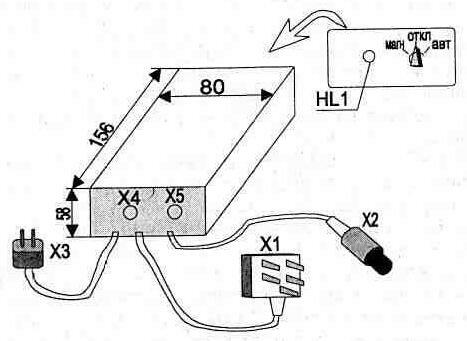
Fig. 2.20
The circuit has resistors C2-23; capacitors C1, C2 type K73-16V 100, NW - K52-1 6, C4 - C50-24 63 In; relay K1, K2 type RES RS4.524.200; switch SA1 type PG-18-SPD. Plug X1 - standard telephone, x2 is widely used in household radio equipment for the transmission sound signals XS - plug any type, socket X4, X5 type G4,0 or similar.
As of the transformer T1 can be used any compact, ensuring sufficient to operate the relay voltage (16… 25) in the secondary winding.
When setting up the scheme may require the selection of resistor R6. For controlling the operation of the machine is used HL1 led that glows when the power to the machine and turns off when you remove the handset from the phone (this is switched by the relay contacts K1.2 network power to the tape recorder).
The appearance of the hull structure shown in Fig. 2.20.
Publication: www.cxem.net