


")

A circuit similar to that shown here was the solution. Although optimised to suit Softcom brand headphones with active noise reduction, it should be suitable for most aviation sets. The plugs indicated are standard aviation types but are insulated from the instrument panel to eliminate earth loops. The inputs from the two pilots' microphones are summed and amplified by transistors Q1 & Q2. When one pilot presses his or her transmit key (mounted on the yoke), the transmit relay (RLY1) closes, muting the other pilot’s microphone via the optocoupler (OPTO1).
Circuit diagram:
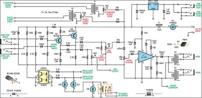 Aviation Intercom Circuit Diagram
The outputs from the microphone preamp, computer audio transformer (T1) and radio speaker transformer (T2) are summed via 10kΩ resistors and applied to the input of IC1, an LM386 audio amplifier. Note that transformers are used here to avoid creating additional earth loops. The output of the LM386 drives the pilots’ headphones via transformers T3 & T4, which are needed for impedance matching. Each audio source has its own level control (VR1, VR3 & VR4). The main volume control (VR5) is included to allow for ambient noise level. VR2 is used to set the signal level for the data logger.
Author: Gary Smith
Copyright: Silicon Chip Electronics