Offer to repeat the device to extend the life of a CRT was designed for TV Sadko-CD", but can be used in TVs and other brands with appropriate changing its connectivity. The main cause of aging of the picture tube when prolonged work - reducing the emission of the cathode. The owner of the TV has the ability to actively intervene in this process and significantly extend the life of the tube. Although this natural process goes under all conditions, its speed can be changed several times depending on the working conditions of the cathode.
Devices, which helps to slow down the emission reduction, offered is a lot. Described below is a device different from them more stable parameters, a wide interval of possible delays reliable protection of the tube against overvoltage and from the device itself circuit. The device include network power button TV. The filament voltage of the tube gradually increases from zero to the nominal value and rigidly stabilized at that level. At the time of his achievements relay, the contacts include a TV and to the anode of the tube enters the accelerating voltage.
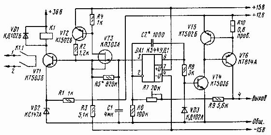
Schematic diagram of the device depicted in Fig. 1. Its basis is the generator of linearly increasing voltage (LVN) transistors VT2 and VT3. The transistors connected in the circuit source repeater with servo feedback. At the time of power-on the stress on the capacitor C1 is zero, and the source of the transistor VT3 (i.e. at the output of the repeater) is about 0.3 V. the Latter begins to charge through the resistor R5, the capacitor C1, and the voltage across it and the output of the repeater is growing. Since the transmission coefficient of a repeater close to unity, the voltage across the resistor R5 is retained approximately constant. Remains constant and the charging current of the capacitor C1. Therefore, the voltage across it increases linearly (non-linearity less than ±1,5%).

Fig. 1
The advantage of the generator can be called small for such a long time delay (about 50) values of elements chain R5C1. This is because the voltage difference on the findings resistor R5, which is charging the capacitor C1, does not exceed 0.3 V and the charging current is also very small (about 0.3 mA). In the same time, the voltage to which the charging capacitor C1, can greatly exceed this difference and is only limited by the voltage power. Temperature stability of gain of the repeater very high due to mutual compensation of temperature coefficients field (VT3) and bipolar (VT2) transistors having opposite signs, and a deep negative feedback.The increase in voltage at the output of the repeater is happening to the level set by the voltage limiter on the VT1 transistor, the Zener diode VD2 and the resistor R1. The level of restriction the Pets equal to: the Pets = East + Uбэ = 4,7 + 0,6 = 5.3 V, where East - voltage stabilizing Zener diode VD2, Uбэ - voltage base-emitter, which opens the transistor VT1. When the output voltage of the follower reaches the value The Pets, closed to the VT1 transistor opens, relay K1 and contacts turn on the TV.
The delay time TV is switched on you can change within wide limits by selection of circuit elements R5C1. In the TV "Sadko - CD" is set kinescope LC-1 with low-inertia cathode. It the heating time does not exceed 12, so the time delay (of about 50 (C) which is provided at specified values of the chain is enough.
Harder of the capacitor C1 is input to the stabilizer the filament current collected at the shelter DA1 and the transistors VT4, VT6. Connection input (output 3) Oh to the capacitor C1 does not affect the operation of the generator LVN because Oh KUA has a very large input impedance. The operation of the stabilizer is to automatically maintain the voltage at the inverted input of op-amp (U2) is equal to the voltage on the direct input (U3). Due to the large coefficient of transmission voltage in the loop return connection stabilizer and precision opamps, voltage U2 and U3 are different no more than units of millivolts.

Fig. 2

Fig. 3
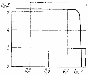
The voltage at the cathode heater of the tube ulo, proportional to the voltage U2, and is equal to u n = U2((R7+R9)/R6)+1). It set a trimming resistor R7. The VD3 diode protects against the breakdown of the emitter junction of transistor VT4 at negative output the stress of the shelter.The operating experience of Zener diodes shows that they may be internal breakage. In case of a break in the Zener diode VD2 the voltage at the output will increase to 11 and In the kinescope may fail. To avoid this, the device has elements protection R10, VT5. When breakage occurs in the Zener diode voltage VD2 the emitter of the transistor VT1 increases sharply, the voltage on the capacitor C1 and the output of op-amp begins to grow, the collector current of the transistor VT4 is also increasing, which leads to increased emitter current of the transistor VT6. The voltage drop across the resistor R10 increases, and at some point opens the transistor VT5, sunterra emitter junction of the transistor VT6. The increase of the collector current ceases. When specified in the scheme the resistance of the resistor R10, the filament voltage is limited to the level of Of 6.8 V. the filament Current is 0.75 A (at nominal 0.7 A), that is quite acceptable. These elements simultaneously protect and transistor VT6 from the circuit. A graph of the output voltage of the device by increasing the load current is shown in Fig. 2.
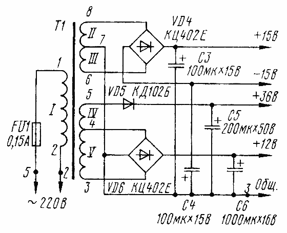
Schematic diagram of power supply device presents in Fig. 3. The numbering of the elements on it continues the numbering of parts device.
The power transformer T1 is formed on the yoke low scatter (with extended bridge) SHU 13x26-40. Winding I has 3000 turns of wire sew-2 0,21; II and III - 230 turns of wire sew-2 0,12; IV - 360 turns of wire sew-2 0.16 and V - 205 turns of PEV-02 0,62. You can also use the magnetic cores of OL, PL and SHL.
In most similar devices, the authors chose the relay on the input parameters (voltage and current operation) and recommend relay RES-9 RES-22. But they are absolutely not suitable for output parameters - voltage, current and type of load. Relay RES-9 active commutes the load with alternating voltage of 115 V and current up to 0.1 A, and relay RES-22 - also active load with variable voltage to 250 V and current up to 0.1 A. However, the TV is a load with a significant reactive component and a current of at least 0.5 A. Therefore, you need to choose a relay designed to switch inductive the load at a voltage of not less than 250 V and a current of 0.5 A. Suitable relay mku-48, RCS-3, etc. In the device used in the relay RTP-100. On output parameters and dimensions, it fits with room to spare. Intended it to work with AC supply voltage of 220V, but, of course, can also operate on DC voltage. To increase the sensitivity three of the four pins removed. The relay is mounted anchor up. For eliminate sticking of the armature between it and the magnetic core are glued film of a nonmagnetic material with a thickness of 0.01 mm. After such modifications the relay is triggered when the voltage of about 30 V and a current of 15 mA.
In the capacitor device C1 - MBGO, C2 - any, C3-C5 - C50-6, C6 - C50-35. The transistor VT6 is installed on the radiator with a surface area of 150 sq cm, and the VD4 rectifier and VD6 - on heatsink with an area of 60 sq. cm Zener diode VD2 is also equipped with an aluminum radiator size 15x20x0,5 mm. Resistors - MLT, except for R10, which is made in the form frameless spiral of nichrome wire with a diameter of 0.4 mm and a length of 20 cm.
Pre-establishing device to begin installing the TV using a dummy load wire the resistor 9 Ohms power dissipation 5 watts minimum. Turning on simultaneously feeding device and a stopwatch, measure the time, through which will trigger the relay K1. If it differs from the desired, need to make a choice of the resistor R5 or the capacitor C1. Trimmer resistor R7 sets the 6.3 V on the dummy load (the limits of it...is -5.9 6.7 In).
In some devices the possibility a significant increase in the filament voltage. This is done to ensure that, speed increasing to 11...13, recover for a while the emission of the cathode. However, this method allows to extend the life of the tube after each step two to three months, but not more than a year, after the cathode irreversibly loses emissions. Specialists it is not recommended therefore, the proposed device mode of increasing the filament voltage not provided.
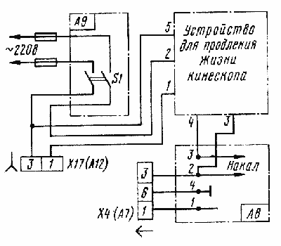
After pre-establish disable the unit from the mains, attach it to a proper place inside the casing of the TV and by the circuit of Fig. 4 connect to his chains. For you need to unsolder the end of the wire coming from the power switch S1 TV connector × 17 (A12), from the pin 1 of the connector and solder it to pin 2 of the device. Then, remove the wire connecting contacts 3 A8 Board with contact 4 of connector X4 (A7), and connect the wire contact 3 A8 Board with the contact device 4, and pin 2 on the card with the contact 3 device. Soldering the wire connecting pin 2 A8 Board with a contact 3 connector X4 (A7), it is impossible, as it on the thread, Kaka arrives the offset voltage +V. 65 Further includes meals, give your device a and the cathode of the picture tube to warm up 10...12 min, measure the filament voltage and, if necessary, set the value of 6.3 V. At this establishment done. It only remains to turn the power off, connect the wire to the contact 1 device with pin 1 of the connector × 17 (A12) of the TV and close the rear cover.

Fig. 4
Author: M. Dorofeev Moscow; Publication: www.cxem.net


