The mode "Electronic magnifier" hams are not often used in their devices to verify and repair emission cathodes tubes. Author of published the article managed to make a simple device that implements such a mode.
Instruments for testing of picture tubes in various technical literature describes very much. However, the known (to the author) only three of the devices [1-3], which provide a check in the "Electronic magnifier". But to repeat them it is not easy. Thus, in [1] does not specify the values of some details and information about a string transformer. Although the device described in [2], it is possible not only to check kinescopes in the "Electronic magnifier", but also to restore their emission cathodes, it therefore, more complicated. In particular, for its production need to be wound four transformer, and especially not easy to make a high voltage transformer. A similar device is described in [3], contains fewer parts, and more compactly. But it requires to reel three transformers, as well as use three rather expensive transistor.
In connection with the above, it is proposed to repeat a relatively simple the device, which also works in the "Electronic zoom" [1,2]. For it manufacturing, except an old flyback transformer may have to reel is still only one low-voltage transformer (if there is not ready) and use only one cheap transistor.
It should be recalled that in the "Electronic magnifier" in the Central part of the screen the CRT light spot appears (projection cathode) circular wrong form. When focusing the images on the screen visible area normal (light uniformly colored areas) and low or high (various blackout, flash, point, etc.) of cathode emission. If the area is dark areas of the image in the recovery of cathode emission begins to increase, the process should be stopped immediately, otherwise it will lead to destruction the emission layer of the cathode.
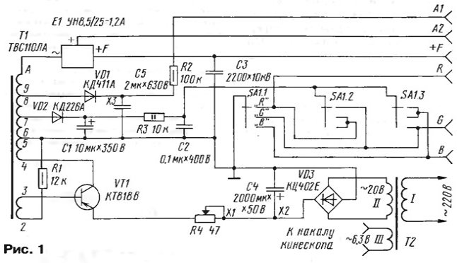
Schematic diagram of the device represented in Fig. 1.

Based Converter the voltage in the device comprise a flyback transformer T1 and a tube TV - TVSE, multiplier voltage E1 and the transistor CTV. And you need to employ the transistor is, the structure p-n-p, so that when using transistor with another structure of the amplitude of the pulses is smaller.
The power transformer T2 is selected based on the conditions for obtaining two voltages 18...20 and 6.3 V at a current of 1 A. the voltage Multiplier ON,5/25-1.2 A - color TV ALPCITY or OPENCT. Capacitor C3 - K73-13, C5 - MBGO. The Resistor R4 Is FG2-12 (wire). This resistor focus the image on the screen of the kinescope. You can take it from the block information of TVs ALPCITY.
Switch cathodes S1 - PG-SPSN. Transistor CTV can be mounted on aluminum frame transformer TSL, only the panel that was inserted the rectifier, it is better to remove.
As the connectors are used contacts from the disassembled panels for PLB the CRT LK. To the terminal A1 is connected check the accelerating electrode kinescope, A2 (standard connector) to the second anode, F - focusing electrode, to the R, G, b cathodes (respectively "red", "green" and "blue"). Modulators of the kinescope leave free. The findings of the filament is connected to filament winding III of transformer T2 via the same connectors.
On the front panel of the device fix the switch SA1, the resistor R4 and the terminal block for connection wires going to check the picture tube.
To check, connect the tube to the device through the respective connectors, and the engine of the resistor R4 is set to the maximum resistance (at right on the diagram). Turn the unit on. After warming up the engine of the resistor R4 derive the projection included the cathode to the screen. The switch SA1 is connected other cathodes and compare their projections. If the CRT is insufficient vacuum, in the flask at the base will be noticeable ionization glow.
The device is very simple to get recovery mode emission cathodes tubes. This requires that the filament winding of the transformer T2 is provided, in addition to the nominal 6.3 V, additional voltage 8; 9.5 and 12.5 V. For them switch add another switch. In addition use another the resistor and the button included in the scheme in Fig. 2.

To the terminal M is connected the degree charge which depends on the position of the focus lever to R4. In one chain from the terminals of the winding II of transformer T2 impose additional switch. It, the switch voltages of the filament and the button SB1 also placed on the front panel of the device.
When restoring the emission of the cathode, first you need to warm up the tube when the rated voltage of the filament (heater) 6.3 In for 5 to 10 minutes At... this should turn off the Converter with additional switch. Then ( the first stage is sequentially fed to the heater filament voltage 8 - at 2 min, 9.5 In - at 2 min, 12.5 V - 1, 9.5 - 30 8 - 30 and finally, 6.3 V. Again include the Converter and check the cathodes of the kinescope.
If the result is not satisfactory, move to the second phase of recovery. First set the engine resistor R4 to the middle position for tubes with screen, less 51 cm, or to the extreme left (the scheme) provision for picture tubes with a diagonal of 51 cm and more. Then choose the switch SA1 worst the cathode includes a filament voltage is 8 V and push the button SB1 four to five times with just a few seconds. Again include the rated filament voltage of 6.3 In and check the recovered cathode.
Literature
Author: S. Voronov, Moscow


