The reception of satellite TV channels is becoming popular and affordable, as demonstrated by the increasing number of "plates", located on the roofs and the walls of houses. Often one satellite dish lovers welcome connecting several subscribers. How to make such connection, and described in this article.
To connect multiple subscribers to a single antenna must be applied special splitters signals. The simplest of them is passive. They popular. Their disadvantage is the loss of signal strength at each of subscribers. And if the cable will be a significant reduction, perhaps the poor TV reception - noises appear on the image in the form of "snow" noise in the sound channel, and even the disappearance of the image.
To address this shortcoming it is necessary to apply additional amplifiers or active splitters. As is known, the range of operating frequencies tuners (wide receivers) satellite television is 0.75...2.2 GHz, respectively use splitters should work in this range. Of course, such devices can be purchased in specialized trade organizations. On the other hand, many of such devices are simple in the manufacture and they are quite capable of making even not too experienced the radio fan, you just have to show the desire and a bit of skill.
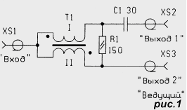
Diagram of the signal splitter on the two lines shown in Fig. 1. He assembled according to the scheme hybrid coupler-based broadband transformer. To the exit divider you can connect two tuners, one of which is a leading (connected to the socket XS3), i.e. the power and control of the block LNB (Converter installed at the receiving antenna) are made from this tuner. The second tuner, connected to the socket XS2, will only receive the signal from the Converter, but not will be able to manage it.
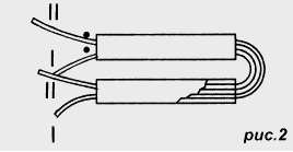
In this arrangement, only one element that will have to make independently, the transformer T1. Its design is shown in Fig. 2. For the manufacture of the transformer will need two tubular ferrite magnetic core length of 10 and a diameter of 2.8 mm, for example, MVN-10 size 2 FRI,8x1x10. Quite suitable magnetic circuits from the normalized high-frequency chokes DM type-1 inductance 40 to 50 micrograms. Through them, as shown in the figure, is passed two cut the wire sew-2 is 0.32, then the tubes are stacked together and connect the beginning one pigtail with the end of another. All findings should be made minimum length.
The resistor (R1) it is desirable to use small-sized metal film, for example, P1-12 or high frequency C2-10 with the conclusions of minimal length. The capacitor also it is desirable to apply high-K10-17B, in the extreme case, km, KD conclusions length of 1...2 mm.
A sketch of the circuit Board of the splitter shown in Fig. 3. Board made from double-sided foil fiberglass 1.5 mm thick, one side her left metallized and serves as a common wire. As the power of the signal is divided, the attenuation at each of the outputs will be about 4...4,5 dB, isolation between output channels - within 12...15 dB.
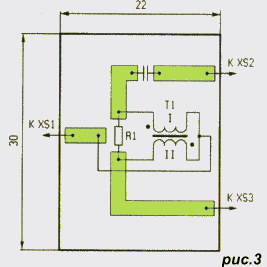
The fee should be installed in a metal enclosure which can be soldered from cuts foil fiberglass.
Input and output jacks are installed in the housing so as to provide the possibility of their Central desoldering pins directly on the Board, place desoldering metallized side of the card is necessary to direct close to the grounding terminal of the socket.
If it should be possible to power and control the Converter from both tuners, the splitter must be performed in accordance with the scheme shown in Fig. 4. Here, the power Converter will be supplied through one of the diodes, which appears when you enable the corresponding tuner. When turned on, and the second tuner power will be supplied from that in which the voltage will be more.
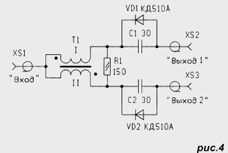
Printed circuit Board for this variant of the splitter is the same as shown in Fig. 3. You will also need to make an incision in the printed wire that goes to the connector XS3, for the installation of the capacitor C2. The diodes are mounted directly on the PCB the tracks on the capacitors, the findings of the diodes must be of a minimum length.
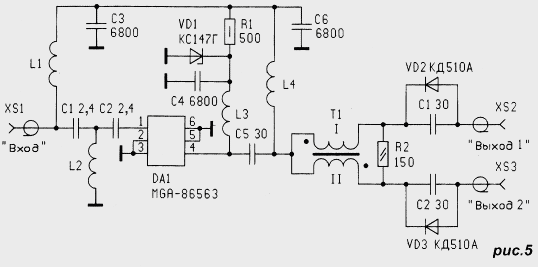
Both of the above embodiment splitters referred to as passive devices, their the application leads to the decrease of the signal level at the outputs. In some cases reception conditions require active splitters, which not only share the signal, but additionally strengthen it. The scheme of such a splitter shown in Fig. 5. It is based on a miniature monolithic gallium arsenide integrated circuit RF amplifier MGA-86563 produced company HEWLETT-PACKARD. Chip is a broadband microwave amplifier with a frequency range from 0.5 to 6 GHz.
Main technical characteristics
- Gain (2.4 GHz), dB 21,8
- Noise figure (2.4 GHz) dB 1,6
- The voltage, V 5
- Consumption current, mA 14
- Output power at compression gain by 1 dB, mW 2
The chip is available in two packages: SOT-143 and subminiature SOT-363. In the latter case, the cost is lower and amounts to a few dollars USA.
Active splitter consists of an amplifier on a chip and hybrid splitter. It is powered by one of the tuners on cable reduction. One of the diodes VD2 or VD3 open, and the voltage across the transformer T1, chokes L4 and L1 is supplied to the Converter. At the same time it voltage is applied and on the parametric voltage regulator elements R1VD1С4 from him through the inductor L3 and the chip is powered amplifier.
On the input circuit set the high pass filter with a cutoff frequency of about 600...700 MHz, which protects it from possible power surges and low-frequency interference on the cable. The gain of the splitter is about 15 dB.
All of the elements of the device is placed on the circuit Board from double-sided foil fiberglass. Its sketch is shown in Fig. 6. The second side left metallized and used as a common wire, through which holes in the circuit Board are connected to some site and printed details.
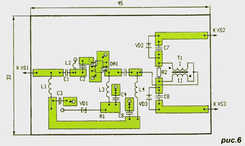
In the device it is desirable to use capacitors K10-17B or similar imported, the resistor R1 is composed of two parallel connected resistor R1-12, MLT or any other with a resistance of 1 kOhm and power 0.25 W. The windings of the inductors L1, L3, L4 is made on the mandrel with a diameter of 2.5 mm wire sew-2 and contain 15 turns, L2 are wound with the same wire on the mandrel with a diameter of 2 mm and contains a 1.8 coil. The transformer T1 has a design described above.
If you need a splitter for four tuners, you should use the scheme divider, shown in Fig. 7.
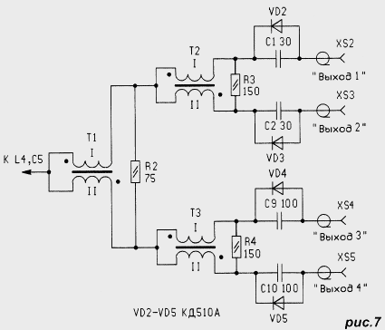
Since in this case the signal on each of outputs are attenuated to a greater extent, the device should be made active. In the quality of the amplifier, you can use the solution according to the scheme of Fig.5. In case the lack of amplifier circuits can be performed on the transistors type CTA-2. Amplifier circuit for this purpose is given in the book by E. red "Handbook of high frequency circuit design", pp. 137 - 139, released the Moscow publishing house "the WORLD" in 1990.


