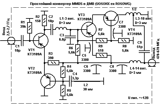
This simple Converter is designed for converting a television signal from the range of 2.5-2.7 GHz range 470-670 MHz. For use close to the transmitting station MMDS. The disadvantage of the simple scheme, the direct passage of the UHF signal induced on the receiving antenna MMDS fixed in the following versions of the Converter. Modified pass-through capacitors are used here as a reference, lying on the Board on top.

The scheme is made in hinged installation. Power +12 volts is applied to reduce cable through a simple LC filter addition.

- the line L2 in the local oscillator is made of tin-plated 1.5 mm wire, which is not from walk-through capacitors completion; - long line L2 is specified for a frequency of 1015 MHz, and the mixer operates on the second harmonic of the lo frequency;
as C4 was used capacitors from 2.2 to 4.4 pF pF and the required frequency were fitted a long line L2;
- type C4 is unknown to me. Structurally, this capacitor is made in the form of a cylinder of 3 mm diameter and 3 mm long, made of white УSW ceramics, and the ends were soldered thick conclusions. When mounting the findings sealed. Just successfully applied the capacitors types KM4 frames and CD-1, but they are significantly less durable;
- the capacitor C2 left one conclusion 10-12 mm long, which is sweet in the coil L1. To Orient the coil L1 must perpendicular to the axis of the coil L3 for minimizing inductive coupling and positioning as far as possible from each other. The resonance frequency of the serial circuit C2,L1,C3 should be around 570 MHz, and its frequency response is wide, with a bandwidth of 200 MHz. This filter is designed to attenuate the penetration of heterodyne frequencies to the input of the HRC, VT3,VT4;
- the contour formed by L3 and the output capacitance of the transistor VT4 plus installation capacity is adjusted by tension-compression of the turns of the coil L3 of mid-range 470-670 MHz. For settings, you must connect a 75 Ohm load and selecting the position of the outlet L3 to achieve a stable maximum gain in a given band. To increase the stability of this node, in the following constructions, I separated the shielding partition coils L3 and L4 from the rest of the circuit. Cascada scheme VT3,VT4 gives high gain and configuring this node is perhaps the most difficult procedure;
- all parts in this diagram are located on one side of the Board directly on top of the tinned foil. Bushing capacitors (external electrode is soldered to the Board) and other grounded parts are used as a fixing and supporting elements for other details;
- on the perimeter of the PCB is soldered 20 mm strip of tinplate, the resulting box with a lid. Cable entry is made via the tube rolled from sheet metal and all soldered fusible solder Post for stiffness and tightness.
As I wrote, this design has such disadvantages:
- no filter on the input allows signals TV UHF freely pass to the output and it is possible to prevent reception of some MMDS channels;
- half the frequency of the local oscillator is not only worse for the conversion, but just as bad is delayed by the filter C2,L1,C3 and through the HRC gets the output of the Converter. Of course, channel filters of the TV is effectively cleaned by the lo signal, but to adjust the frequency response of the Converter with the included oscillator is simply impossible.
So I continued to improve this Converter and made two more, a better option is simple and with balanced input. And yet, it is this page on my website remains the most visited. Apparently impresses the apparent simplicity of the design, wherein the repetition even novice radio Amateurs who do not have other measuring devices in addition to tester. Enthusiasm is commendable, but personally I microwave technology began only after 20 years of radio design. In developing their designs, I used the generators, frequency counters, and measuring the frequency response of the respective ranges. To repeat, of course, easier, but I'm probably one tester could not well set up the UHF Converter.
However, I wish you luck!
Author: E. shoustikov, UO5OHX ex RO5OWG; Publication: www.shustikov.by.ru, www.cxem.net


