I will put the questions and answers on the designs of my 3 Converter for MMDS TV - simplest, simple, with balanced input.
- please clarify how best to apply the offset to the base of VT1, VT2 MMDS converters, manifolds or flow capacitors?
There is almost no difference, how to file offset. For the latest converters I took a very small resistors MLT, taking a bite of the conclusions on "the zero removed the paint and the rest of the findings, tinned the tip, was placed on top of the transistors and their findings are soldered to the ends of the end walls of the resistors. And have them connected the other elements.
- please indicate the approximate currents through the transistors of this circuit?
The modes of the transistors (except VT4) are set automatically. Currents are approximately as follows: VT1 - 4 mA, VT2 - 7 mA, VT3 - 15 mA, VT4+VT5 - 15 mA. Offset VT4 need to be chosen according to the maximum transmission rate of the mixer (near 0 current).
- if possible please describe in more detail how to configure the Converter.
Setting start with the HRC UHF (VT5,VT6). Using the select meter response position drain output coil HRC, achieving a maximum and uniform gain in the range 470-670 MHz. The signal is fed to the input of the mixer VT4. Capacitor C16 together with its findings should resonate in the middle of this range. Connect the local oscillator VT3 and to zero-beat with the generator 2030 MHz expose its frequency. Connect UHF VT1,VT2 and finally configure the Converter feeding the 2500-2700 MHz signal to the input. Coupling capacitors UHF conclusions should resonate in the middle of this range. Resonance in the circuit "fuzzy", so a length of pre-customize their findings outside of the scheme. The signal generator includes a modulation that is seen on TV as a broad horizontal stripes. Gradually reducing the signal level adjust circuit for maximum contrast stripes. In the absence of the devices you can try to configure the HRC on the signals of UHF television and the frequency lo to look up to the "hit" MMDS transmission in UHF channels. Of course this is only possible in coverage.
why I use transistors of different conductivity?
- to specify the size of elements:L1,C14.
In the Soviet Union, I bought 200 PCs of transistors CTA in store Junior Technician at 65 kopeks thing and still happy with it. Many microwave designs have been used, where possible. It turned out that they provide 16 dB gain on UHF. And even generate 2.5 GHz! Well, in the input circuits, I used a transistor is more suitable for 2600 MHz, relying on their low-noise properties. So that different conductivity is not an end in itself, just cheaper.
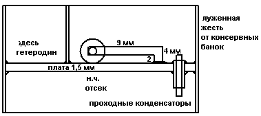
Line L1 is made of tin-tin (copper or silver :-)) in the form of an l-shaped box 9 mm long and 2 mm down to pripiski to the Board, directly to it without pins soldered pellet capacitors C1,C2 type KD-1. On Board line is 2 mm, however the rest the same. Capacitor C14, also the tin box is bent at right angles and soldered to the base of VT4, and its capacitive Playground adjacent to R9, side emitter VT3.
Pictures:

Fig. 1

Fig. 2

Fig. 3
Author: E. shoustikov, UO5OHX ex RO5OWG; Publication: www.shustikov.by.ru, www.cxem.net


