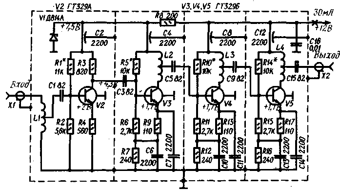
We offer our readers the antenna amplifier is designed to amplify signals of radio and television broadcasting stations meter band.
Main technical characteristics of the amplifier
Bandwidth. MHz. with the weakening of the signal at the edges of the range 3 dB....50 350...
Noise level, dB....3,5
Input resistance, Ohms....75
The nominal load resistance, Ohm....75
The gain of the voltage signal of 5 mV, dB, at frequency, MHz:
48....39
230....41
Schematic diagram of the amplifier is given in the figure. He collected four transistors connected in the circuit with common emitter. A feature of the amplifier is used as the collector loads of the transistors V3-V5 inductors, thus reducing the blockage of the amplitude-frequency characteristic (AFC) of the amplifier at higher frequencies.

The amplifier can operate under a supply voltage up to 4 V. In this case, the gain across the frequency range is reduced to 36 dB. To operate the amplifier at a low voltage Zener diode DA must be replaced by XA or KS147A. The current consumed from the power source, will be reduced in this case to 15 mA.
The amplifier is mounted on four boards dimensions h mm from bilateral foil fiberglass 2 mm thick. One of the sides of the Board is used as a screen. Motherboard installed in the rectangular recesses brass body and separated from each other by baffle plate, soldered directly to the foil surface of the boards.
Coils L1, L2, L4 contain 2.5, and L3 - 4 turns of wire PEL of 1.0. The diameter of the winding coils L1-L3 - 12, a L4-20 mm winding Pitch is 8 mm.
The establishment of an amplifier start with the set-up transistors DC in accordance with those in his scheme. Then proceed to adjust the AFR. You can use devices X1-19A, X1-1. TR-0813 or sweep any type.
At sweep sets the selected frequency range with a maximum swing band. The input of the amplifier serves voltage of 5 mV (this signal corresponds to the device X1-19A the attenuation to 50 dB). Setup of the amplifier is reduced to the selection of places of taps of the coils L1-L4 to obtain the desired pause transmission. The AFR can be removed using a calibrated generator of standard signals and a vacuum tube voltmeter, Secunderabad last resistor 75 Ohm (see article I. Gehenna, V. Kolomiets and N. Savenko "Antenna amplifier with remote adjustment" in "Radio", 1975, No. 4, pp. 15, 16).
Authors: Yu Beelden, A. Danilov, C. Seitnepesov, Ashgabat; Publication: N. Bolshakov, rf.atnn.ru


