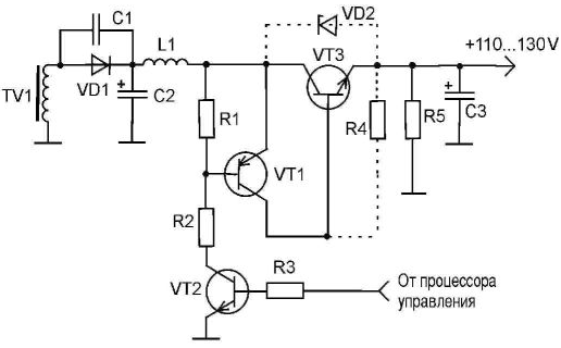
In many monoplane color TVs with a screen size of 14, 20 or 21 inch production companies such as LG, Akai, Samsung, Funai, JVC, and Condor some others, when you switch the TV to standby mode switch voltage horizontal sweep of the television. However, the absence the voltage at the output of the switch corresponds to switch the TV to standby mode.
This switch, usually performed according to the scheme shown in the figure. In as transistors are used VT1 type 2SC1013, 2N5401 or A; VT2 type 2SC2230; VT3 type 2SC3310 or BUT11АХ. The switch is made the signals of the processor control TV input at the resistor R3. When it is in the working mode of the TV +5 V (log/T) at the output of the processor control corresponds to the enabled state of the horizontal sweep of the television. In standby mode the TV is a control voltage is less than 0.4 In (log."0").

The voltage log."1" through the resistor R3 opens the transistor VT2, which connect to GND TV resistor R2. As a result open transistors VT1 and VT3 and the input voltage to the switch of the capacitor C2 to capacitor C3. The input voltage to the switch is supplied with winding of the transformer TV1 mode power supply of the TV. Output the voltage from the emitter of the transistor VT1 is directly fed to the output the cascade horizontal and TDKS. Resistor R5 accelerates the discharge of the capacitor C3, and VT1 structure p-n-p, which then leads to damage to power transistor VT3. Sometimes failure is just the power transistor VT3.
The most unpleasant option: VT1 not penetrated completely, and only loses its amplifying properties and does not open fully at the signal log."1" from CPU management. This leads to incomplete opening of the transistor VT1. The current base VT3 is insufficient, whereby the voltage drop across this the transistor reaches 10...20 V. there is intense heating of the transistor, which may even lead to charring of the PCB at the mounting location VT3.
Repairing this TV, it's hard to resist the temptation to replace the switch electromagnetic relay, the winding of which is connected between the collector of VT3 and power source of +12 V. However, the use as a switch such widespread electromagnetic relay, as the RES-9 or RES-42, allows to recover the TV only for a short period of time - 1...7 days. After that there is the “sintering" of the relay contacts and switch stops working: its output voltage becomes equal to the input. A more powerful electromagnetic relay in this case is impractical because of the large power consumed their control windings, and a significant dimensions.
When repairing the switch have to deal with a situation where a simple replacement of defective transistors does not help. Some time after repair TV again fails. Besides, applied in the switch HV imported transistors are quite expensive and not universally available in sale. Therefore, to restore functionality of the switch can to apply the transistors of domestic production: VT1 type CTM, VT2 type CT only with the letter G, VT3 type CTA. In addition, the switch scheme it is desirable to Supplement the resistor R4 C2-23-0,125 watt 470 Ohm nominal and Zener diode VD2 type XA or similar (shown by a dotted line). The VT3 transistor and a Zener diode VD2 should install through the insulating strip on the radiator output transistor horizontal.
Typically, this l-shaped radiator plate has a very large area so the problems with deployment of additional elements does not occur. A transistor and a Zener diode must be placed away from the location on the heatsink of the output transistor horizontal so as not to worsen it the thermal regime. Transistor VT3 is desirable to install on the radiator, even if as it uses imported unit. With the pins of the transistor should be connected to the circuit Board of TV wires with a diameter of at least 0,25...0,35 mm2.
After this upgrade the switch in a situation when power surges happen the supply network, the voltage on the transistors VT1 and VT3 voltage will be limited stabilization VD2, i.e. 120 V. during voltage fluctuations in the supply the network maybe a slight increase in the voltage at the output of the switch 30 to 40 V. However, this small voltage does not lead to the beginning of the horizontal sweep. Moreover, the current flowing through the Zener diode VD2 and the resistor R5 causes lowering the voltage on the capacitor C2 and thus protects it from breakdown.
Author: A. J. Saul, Kiev


