When repairing and improving old domestic TVs, especially when replacing individual units with new, more reliable and modern can be problems related, in particular, using the last three-level pulse signals (gate pulses). How to solve them, you learn from published articles here.
Three-level pulse signals for control and synchronization of the building blocks have long been used in equipment household video. Ignorance or disregard of this fact sometimes brings a lot of trouble when upgrading or repair.
What the developers began to use more complex command signals? At first glance, this is a clear deviation from the principle of continuity and unification of units of one and the same purpose. However, from time to time life compels us to make such a radical change. The developers themselves explain this by minimizing the number of leads of the chips and connections between the blocks, specified in the B. N. Khokhlova "decoders color TVs" (M.: Radio and communication, 1992).
For example, a videotape recorder PANASONIC NV-SD300AM contains the processor chroma AN3553FBR, which has 84 output coming out of the building on four sides. Obviously, there is reason to reduce their numbers. By the way, for example, the output 53 of this chip is a three-tier command input to select one of three standard colour video signal processing.
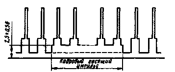
In domestic television sets known to many gate pulse for the block of color devices of the second generation was a duplex. Its meant as a signal SC. Personnel blanking pulses received to a block of chromaticity via a separate wire and a contact interconnect connector. Then in some models of the third generation and all TV fourth generation fully adopted the three-level strobe signals, containing both human blanking pulse, as shown in Fig. 1.

Fig.1
Three-level strobe signals was used to designate the SSC and call superstability (super sand castle). Inside the chip (CPU chromaticity) this signal is analyzed in a special node decoding on levels, and the resulting pulses are directed to the areas of the chip where they are needed.
When upgrading TVs, and especially tract chroma, and encounter compatibility issues with the blocks of different generations. But such modernization is often very necessary for some models. For example, this applies to the TV "Horizon 355" in the color which is used very capricious hybrid microassemblies on ceramics. Moreover, the unit radio channel is quite reliable.
Of course, every Amateur radio operator - the owner of TV - tends to hold its alteration with minimal cost. This variant of modernization and presents the greatest difficulties. First, blocks of colour and a radio channel (for example, the specified TV) are located on a common circuit Board, and need to divide them neatly in the holes without damaging the unit radio channel. Secondly, we need a new inter-connector, which is a new block of color with the old radio channel and the total cross-Board. When it is determined that fee block the chromaticity of the fourth generation does not contain the amplifier and therefore requires replacing the picture tube for a new one, where they are available. In addition, it appears that the new color block is no longer necessary personnel blanking pulse. However, it should not jump to conclusions.
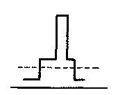
If the screen image becomes visible stripes reverse rays and some distorted colors, it is clearly not enough personnel blanking pulses. Here lies the main difficulty when upgrading. The fact is that on the oscillogram (Fig. 2) the signal SC looks just like SSC and more rare due to the emergence of human blanking pulse in the three-level signal (barely visible thin horizontal line in the lower wide part of the pulse, shown by the dashed line).

Fig.2
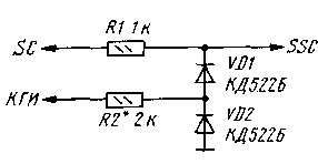
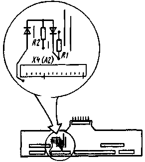
To obtain the signal SSC is necessary to add personnel blanking pulses to the signal SC, using a simple knot which is schematically shown in Fig. 3. It collect surface mounting on the PCB interconnect is A3 as shown in Fig. 4 (a connection point of the diodes and resistor R2 is above Board). To do this, remove the jumper connected to pin 4 of connector X4 (A2), and instead solder the resistor R1 of the node. Point with signals SC, THD and common wire are located in the vicinity of the removed jumper. Only have to drill one or two additional holes in the Board.


Fig.3-4
If you have no oscilloscope, in series with the resistor R2, temporarily solder a variable resistor of 10 kOhm, and his slider set to minimum resistance. When establishing rotate the engine until the disappearance of the lines of reverse rays to take the picture, i.e. to restore the normal color image on the screen. Then measure the total resistance of resistors (AC and DC) and solder them instead of a constant resistance of about 5...10% higher than the measured.
If there need to oscilloscope triggering his pulse output from the node-shaper and achieve (variable resistor) to a thin horizontal line passing through the accurately synchronized impulse SSC, has declined to its widest part (see Fig. 2) and took up a position about 2/3 of the height of this part.
However, modernization does not end there. Still need to make a pair of adjustments of brightness, contrast and chromaticity with a new unit. It seems that for radio Amateurs, ventured on this mess, the last stage will not be much difficulty.
Author: S. Tuzhilin, Moscow; Publication: N. Bolshakov, rf.atnn.ru


