


")

From November 14, 2003 First channel of Russian television began regularly to transfer a number of programmes with stereo sound. They marked on the image with a special icon in the form of superimposed with an offset of one on the other two stylized TV screens. Of course, survived and transfer a mono audio signal.
This broadcast was made possible with the introduction of Ostankino TV tower new the transmitter instead of the old, working since 1967. - from the first day of broadcasting from television center at Ostankino. The old transmitter will be used as backup.
Residents of Moscow and Moscow region can take the stereo, if their TVs equipped with a demodulator - decoder NICAM signal transmitted by way phase DQPSK modulation on a subcarrier frequency of 5.85 MHz. Recall that the spacing between the carrier frequencies of the image and the normal mono audio in the radio channels is equal to 6.5 MHz used as provided in the standards D (MB) and K (on UHF).
About how is formed, is transmitted and received stereo signal sound NICAM described in this and subsequent parts published material.
Until recently in our country was not conducted stereophonic sound support live television programs, so the interest in such systems broadcasting was small. While abroad they are successfully used. One of the most popular among them is the stereo sound system support television broadcasting NICAM (Near Instantaneously Companded Audio Multiplex - almost instantly komandirowannyj audio signal with a seal). It was developed by the British broadcasting company BBC (bi-Bi-si) and for the first time presented in CCIR in 1987 In operation she joined in 1988 and is now widely used in the UK, Sweden, Denmark and other European countries as well as in terrestrial and satellite television broadcasting.
Glossary of terms
- Discretization representation of time-continuous analog signal in the form sequence of discrete values (samples or samples), the following at specific intervals.
- The differential coding method for encoding, wherein the communication channel convey the value of the digital code of each sample, and the difference between the actual value of the current count and value of the same reference predicted by previous.
- Quantization is rounding the value of each sample to the nearest level the quantization.
- Komandirovka - dynamic range compression of the signal during its transmission and the extension at the reception.
- Multiplexing - the combining of multiple input streams into a single output.
- Countdown - single value of the signal obtained by sampling in selected time.
- Digitizing is the procedure in which the reference value is represented in the number corresponding to the number of the obtained quantization level.
- Interleaving bits (bit-wise interleaving) is a permutation of bits, symbols, etc.
- Scrambling (randomization, encryption) - special processing digital signal by moving bits, segments, blocks, or add stray signals such as pseudo random sequence, then the receiver ceases to take it before until this signal is not subjected to diskriminirovaniya.
- Word is a sequence of bits corresponding to the unit of information in digital form.
- The level of quantization - value of the DC signal level of each reference.
- Parity bit - a bit that is used to test the presence of bit error by the addition of one bit.
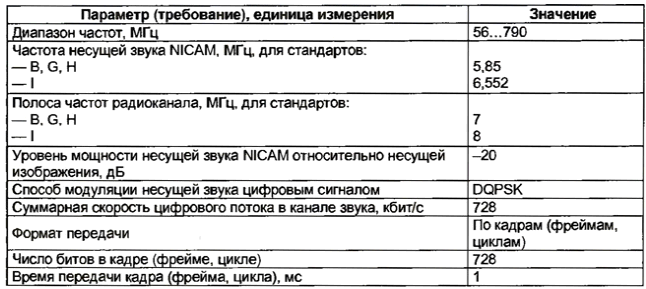
Since the "First channel" television broadcasting started stereo the sound of some of my gear for this system, you should to familiarize the reader with the principles of the formation of the NICAM signal, its transmission and reception of radio-frequency standards B, G, H, I, as well as specific schemes decoders of television signal receivers. Because the system is ensured the total transmission rate of 728 kbit/s, in the literature it is often called NICAM-728 [1 - 4].
In accordance with the Recommendation 707 CCIR system used in those cases in terrestrial television device together with the transmission of analog video signal additionally you want to enter digital audio. For transmission using two carrier frequencies (Fig. 1), most of which f3 DOS modulated, as usual, frequency analog mono audio signal television programs, and additional f3 supplementary digital stereo a NICAM audio signal.
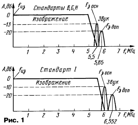
The carrying value of the sound are shifted relative to the image bearing fиз 5.5 (primary) and 5,85 (optional) MHz for standards B, G, H, and at 6 and 6,552 MHz for standard I. On this one NICAM carrier provides the transmission of two high-quality audio signals of the channels L (left) and R (right). Carrier sound NICAM in the standards B, G, H, I is the frequency of the carrier just above usual sound, but within the bandwidth of the radio channel. The main parameters system NICAM indicated in the table.
The principle of formation of a signal system NICAM consider a simplified structural diagram of the transmitter shown in Fig. 2. Prior to submission of the channels L and R analog audio signals on a multiplexed ADC in each of them enter pre-emphasis. They are necessary in accordance with international standards (Recommendation J. 17 CCITT), to provide a lifting RF components signals. Pre-emphasis can reduce the level of noise, which are located mainly in this interval. At the receiver, the ratio of LF and HF components recovering chains pre-emphasis correction that reduces the amplitude of the RF components.
(click to enlarge)
It is known that to obtain high sound quality home hardware enough band of sound frequencies 15 kHz. It follows that a maximum sampling rate (samples) when you convert analog sound waves protein-to-digital signal should be equal to twice the value of the upper sound frequency, i.e., 30 kHz. However, in practice, to prevent the overlapping of the spectra signals and associated distortion use a slightly higher frequency sampling 32 kHz.
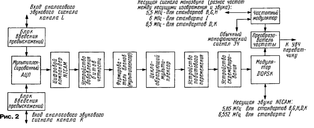
The sampling of the signals L and R simultaneously, then the ADC from the group three samples of the signal L is converted into 14-bit encoded word, followed followed the same group of samples of the signal R, then the L word, etc. alternately. The output signal of the ADC comprises sequentially the following segments data representing a group of 32 samples each channel. 14 bit the digitization of the signals allows to obtain a large number of quantization levels (16384), which is quite acceptable for high quality sound reproduction.
In these circumstances digitizing signals with a sampling rate of 32 kHz is required quite large data transfer rate and, consequently, a very wide bandwidth frequencies, which does not fit into the bandwidth of the radio channel. So on practice using near-instant digital komandirovka (and what specifies the name of the system), which allows to reduce the number of bits per sample with 14 to 10 and bit rate data transfer without compromising quality reproduced signal.
Method of digital companding is based on the fact that the value of each bit binary code depends on the signal level of the sound at each moment is a specific encoded reference frame. So, at loud sounds, etc E. for large signal amplitudes, the influence of low-order bits is very small and can be neglected. When quiet sounds (the values of the samples does not exceed 100…200 mV) LSBs can not be neglected.
Consequently, digital compander NICAM converts the 14-bit code in 10-bit: for weak signals the saved original 14-bit samples, and for signals with great level dropped from one to four bits.
For more efficient companding in some cases exclude some the high-order bits. For example, the 13-th bit will be excluded if it coincides with the 14th; the 12th bit - match and 13-m and 14-m, etc. of the 14th bit is always present, as it indicates the polarity of the signal. When removing the high bits in the system is provided a method of recovery in the receiver, called encoding scale multiplier. It is trecutului code that tells the receiver the number of excluded bits for subsequent recovery.
The next stage of signal processing is to add code to each sample the parity bits and the formation of the 11-bit code. Parity bits required for check six bits to the presence in them of the error.
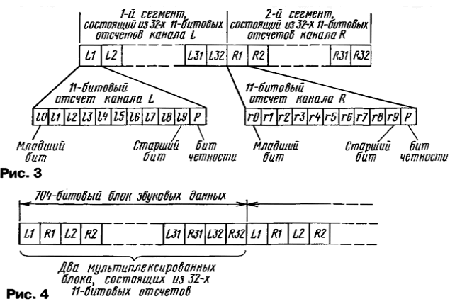
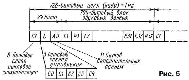
The output device adding parity bits from 32-bit 11-bit counts L1 - L32 (L channel) and R1 - R32 (R channel) formed a group called segments (Fig. 3) which are supplied to the driver units, and then - collabrasuite multiplexer. Before the formation of cycles (frames, frames) the data flow is organized in 704-bit blocks of data, each of which contains two segments (one from each channel), and the blocks are multiplexed so, as shown in Fig. 4.
Before each block of audio data placed additional 24 bits of information required for synchronization and control (Fig. 5). The word cyclic sync synchronizes the receiver for NICAM TV and always has the value 01001110 and bits C0-C4 are needed to control and synchronize the decoder, and the bit WITH called the flag of the cycle.
Next, apply a bitwise interleaving. It is required to minimize bit error (package-error), which are caused by noise and interference and can distort several neighboring bits. The device bitwise interleaving separates adjacent bits from the 16 cycles synchronization (i.e. between them is 15 other bits). Therefore, because the packet error usually does not exceed 16 bits (and it the most likely), it will be dispersed in different readings a single bit error, and it has almost no effect on sound quality.
The device bitwise interleave contains the main memory, where data is first written 704-bit block, and then read from it in the above sequence. The order of reading is stored in the ROM, otherwise called sensor sequence of addresses. Same ROM used in the TV to restore the original bit sequence.
In order that the signal was perceived as random, i.e., have a uniform the distribution of energy, and to reduce the impact on the signal sound NICAM normal the audio signal from the frequency modulator bit stream passes on the scrambling device. It is obvious that the scrambling is not exposed bits the frame synchronization word. The TV is the reverse procedure called diskriminirovaniya bits audio data to restore them in original form.
In the system NICAM for transmitting a digital signal on a radio channel used method phase manipulation of the carrier sound QPSK (Quadrature Phase Shift Keying - quadrature phase shift keying). However, the scrambled digital stream svyazannyh before feeding to the modulator is subjected to a differential encoding, so manipulation is also the name of the differential (Differential) - DQPSK. This is to ensure that the TV could to use synchronous demodulation, but also more simple - difference.
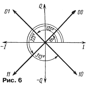
Phase shift keying is the most economical form of modulation in which the frequency the carrier remains constant, while its phase is changed in accordance with the state of the data bits. Quadrature phase shift keying, also called four-way, four phase values: 45°, 135°, 225° and 315°. For them obtain a first carrier phase shift of 90° and form two are in the quadrature data signal: I and Q. the result is a signal with a resultant phase 45°. Then, to the resultant formation of the other of these two vectors the signal is subjected to a phase change of 180° (Fig. 6). Each of the vectors can to be represented by two bits of the binary number:
- 00 - 0° (no phase changes);
- 01 - a phase change of -90°;
- 10 - change phase -270°;
- 11 - change phase at -180°.
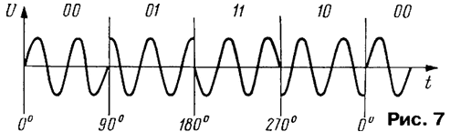
Consequently, the presented bit combinations change the carrier phase on different angles with respect to the phase of the previous signal, as shown in the time diagram of Fig. 7. To ensure that such manipulation phase includes the conversion of the serial stream of digital svyazannyh in parallel dvuhmetrovy format. Resulting bit rate is reduced in two times, which leads to the narrowing of the band of frequencies occupied by the signal.
DQPSK modulated signal and frequency-modulated mono output signal is received on the frequency Converter, where they are transferred on a given carrier frequency. HF the signal is amplified and radiated by the antenna.
Consider a fragment of the structural schema of the TV with integrated demodulator and the NICAM decoder (Fig. 8).
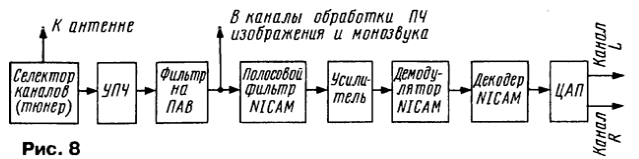
As usual, the broadcast television signal arrives at the antenna input channel selector (tuner), in which there is a choice and to convert received RF signals at the frequencies of image and sound. Reinforced and passed a saw filter they pass to the appropriate processing paths of the TV.
Bandpass filter NICAM (the frequency of 5.85 MHz for standards B, G, N, D, K or 6,552 MHz for standard I) allocates frequencies NICAM, which after amplification come to the NICAM demodulator (Fig. 9). His work is based on the same the principles as conventional FM demodulator of signals in which a phase change or frequency fluctuations result in a change of the output DC voltage. However when quadrature modulation in addition to the in-phase phase detector is used and quadrature phase demodulator, which includes phase-shifted 90° the signal from the carrier generator.
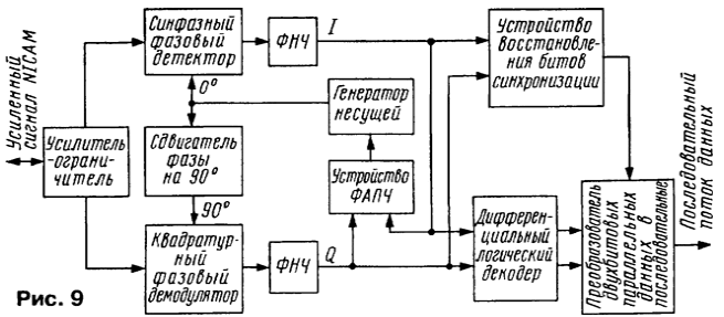
From the outputs of the detector and demodulator through a low-pass filter the data signals I and Q come on differential logic decoder device recovery bits synchronization and device PLL. Last, as usual, if necessary produces an error signal that adjusts the frequency and phase of the generator carrier. Restore device synchronization bits included in a second loop PLL, synchronized with the bit rate. To ensure synchronization of bit rate as the system uses the frequency a multiple bit-rate. Bit rate is obtained by dividing the system clock by 8.
Differential logic decoder converts the data streams I and Q relevant dvuhmetrovye parallel data, which then pass on parallel-serial Converter, restoring the original the serial data stream.
In the NICAM decoder (Fig. 10) provided by diskriminirovaniya, deteremine, that data, restore the original 14-bit words and management DAC.
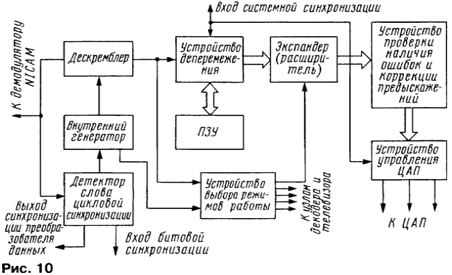
The encoded data from the demodulator NICAM arrive at the detector cyclic words synchronization and descrambler recognition cycle and diskriminirovaniya. Diskriminirovaniya data arrives on the device deteremine, the output which reproduces the original two-channel (L and R) data together with the signal recognition of the radio channel. For deteremine, by analogy with the transmitter, first is the entry in the cell of the ROM data stream block by block and then for reproduction of the correct order of bits of the contents of the cells is read in accordance with the recorded in the ROM program.
Diskriminirovaniya these are also the device of choice of operation modes, which decodes the control bits C0-C4 (see Fig. 5) and transmits the information about the type of transmission on the expander and the other nodes of the decoder and the TV. In it, particular, is formed a lock signal channel mono audio when receiving stereo. This lock prevents the amplifier 3H interference and noise from the channel monaural sound.
Restored in the correct order device deteremine each 11-bit the word (recall: the 10 data bits + 1 parity bit) is expanded by the expander to 14-bit format. The expander uses a scale multipliers inherent in parity bits, which extend 10-bit codes of the samples up to 14 bits.
The device checks for error correction of the bit stream are used the parity bits.
Then in the data adjusted pre-emphasis and they are received by the device control DAC, which generates three signals: bit stream of the data signal recognition and synchronization signal.
Usually use one DAC operating in turn on code word signals L and R. the outputs of the DAC analog signals are formed 3H, and served on the corresponding power amplifiers.
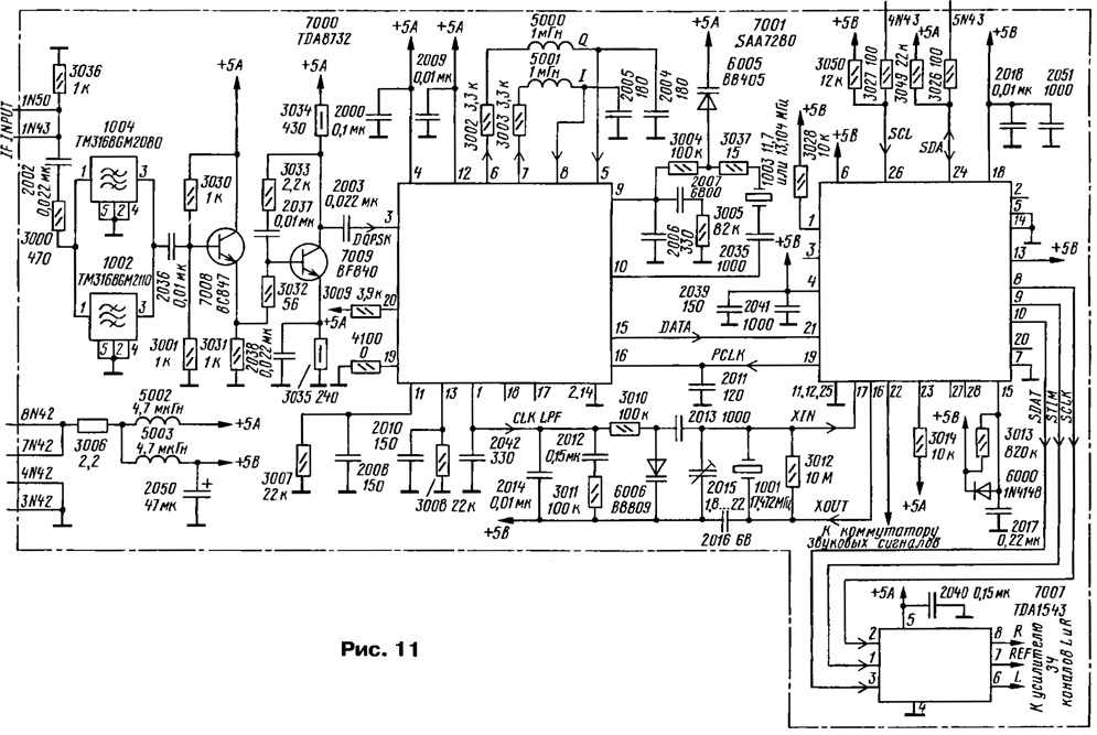
Consider now the schematic diagram of the receiver for NICAM (fee) TV PHILIPS - RT-W/42(58) assembled on the chassis FL2.24, FL2.26 or FL4.27 (AA) (Fig. 11). The receiver is designed so that it can process signals as standards B, G, N, and standard I.
(click to enlarge)
The input pins on the card 1N43 and 1N50 (IF INPUT) submitted the if signal NICAM. Two a bandpass filter 1002 and 1004 connected in parallel, provide the allocation signals of the above mentioned standards. Cascade transistor plays a role 7008 emitter follower and transistor 7009 - amplifier frequencies.
Further, the NICAM signal (DQPSK) is supplied to pin 3 of IC 7000, performing the function of demodulator components NICAM sound spectrum. It happen recovery time slots (bits) of the digital code, conversion parallel code data signal in a coherent and phase locked loop the oscillator frequency is twice the carrier.
Block diagram of the chip TDA8732 depicted in Fig. 12. Through the amplifier-limiter chip inside the signal reaches the common-mode phase the detector and the quadrature demodulator. One of them filed a subcarrier signal without phase change while the other is shifted by 90°.
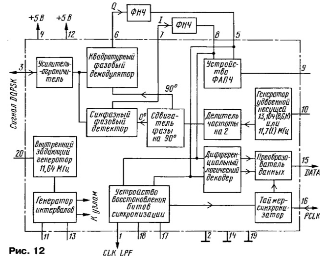
Formed at the outputs of these devices signals I and Q via terminals 7 and 6 chip, the low-pass filter (choke 5001, 2005 and the capacitor the inductor 5000, capacitor 2004 in Fig. 11), findings 8 and 5 chips are on the differential logic decoder (Fig. 12), the device recovery bits sync and the PLL device. The first converts in parallel the received signals I and Q in dvuhmetrovye digital data, and further included a data Converter restores them to their original sequential stream.
The device will restore bits CLK LPF (pin 1 of the chip) included The low-pass filter (capacitors 2042, 2012, 2014, resistors 3011, S) and a varicap 6006 (see Fig. 11). Under the influence generated at pin 1 of the chip level voltage the capacitance of the variable capacitor is changed, resulting in automatic adjustment of the quartz resonator 1001. This ensures synchronization word detector cycle synchronization in the chip 7001.
To the output of the PLL device (pin 9 IC 7000) connected to the low-pass filter (capacitors 2006, 2007, resistor 3005) and a varicap 6005. Under the influence formed on pin 9 of the chip of the voltage level of the capacitance of the variable capacitor is changed as a result which automatically adjusts the frequency of a quartz resonator 1003, and therefore, and generator to twice the carrier frequency (Fig. 12). So is the system synchronous demodulator.
The data Converter IC 7000 synchronized external word clock PCLK supplied to the timer / synchronizer via pin 16 of the chip (see Fig. 11) with internal oscillator of the chip 7001.
The serial data stream DATA from the pin 15 of the chip passes through 7000 conclusion 21 7001 chip (Fig. 13) on the detector of the word and frame synchronization descrambler. The work of most devices chip SAA7280 matches already narrated by Fig. 10 in the previous part of the article and comments is not required.
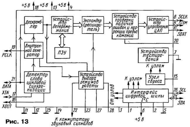
It is only necessary to add that with the device of selection modes through the output 22 of the chip (see Fig. 11) control voltage is supplied to the switch audio signals and provides a channel lock common mono sound when stereo. The remaining outputs of the device mode work (see Fig. 11 and 13) in this particular TV is not used.
Device 7001 chip are controlled by the digital bus signals 1C, so inside the chip provides the interface of the tire (Fig. 13). Signals sync SCL fed to it via the output 26 of the chip (see Fig. 11), resistor 3027 and contact 4N43 Board, and the signal data SDA received and removed via the output 24 of the chip, resistor 3026 and contact 5N43 Board.
With the control device DAC chip 7001 (Fig. 13) via the terminals 10, 8, and 9 digital data signals SDAT, sync SCLK and recognition STIM respectively are on pins 3, 2 and 1 chips 7007 (TDA1543), performing the function of the DAC. At its outputs (pins 6 and 8) are formed of sound stereo signals of the left (L) and right (R) channels supplied to amplifier 3H.
(click to enlarge)
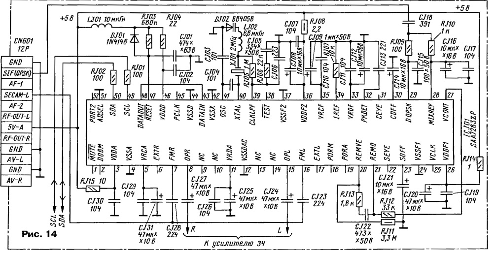
In Fig, 14 shows a portion of schematic diagrams of your sound card (AUDIO) SAMSUNG TVs - CS6277PF/PT collected on the chassis SCT51 A. it Should be noted, in the demodulator-decoder all fixed resistors, except RJ08, RJ11, and all non-polar capacitors are used in the performance surface mount (CHIP). Channel signal processing NICAM built in TVs on a single LSI ICJ01 (SAA7283ZP) performing the functions of a demodulator of DQPSK signals, decoder the demodulated signals and DAC (Fig. 15).
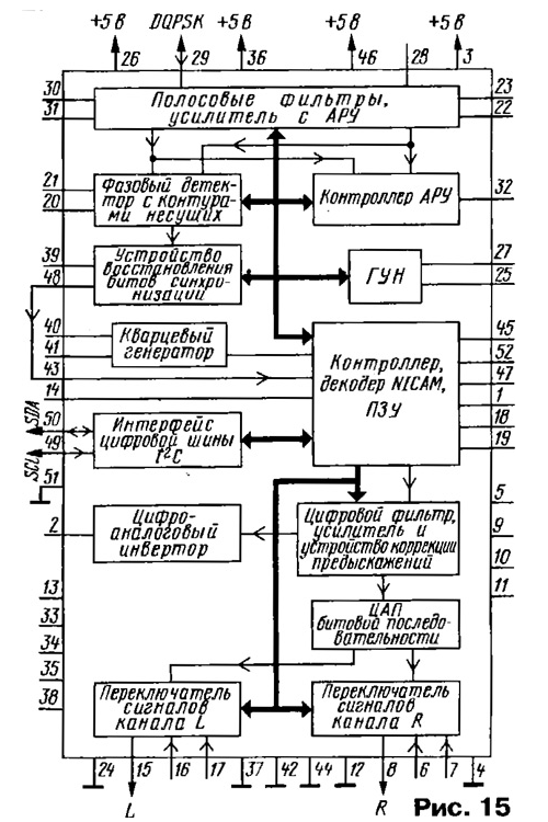
Quadrature (phase) modulated signal NICAM DQPSK through contact SIF(QPSK) connector CN601 (see Fig. 14) the sound card and the output 29 of the chip (Fig. 15) enters the built-in bandpass filters (5,85 and 6,552 MHz) & covered by the ARU and managed internal AGC controller.
The DQPSK signal is detected by the phase detector with the contours of the bearing, on which (in depending on the adopted standard) generates an error voltage, subsequently transformed VCO control voltage (in our case at pin 27, see Fig. 14). It affects the chain adjustment circuits.
The generated signals I and Q come (see Fig. 15) on the restore device bits sync that via terminals 39 and 40 of the chip affects a crystal oscillator.
In the NICAM decoder is diskriminirovaniya, deteremine and that the data signals. The decoded data after the digital filter are amplified, pass device pre-emphasis correction and converted built-in chip DAC into analog audio signals of the channels L and R. passed through the output switches the signals L and R from the terminals 15 and 8 of the chip, respectively arrive at the amplifier 3H.
On the output switches can be served and other signals, e.g., the monaural signal of the normal sound in the absence stereo support. In this module via terminals 7 and 16 of the chip, capacitors and CJ28 CJ23 and contact SECAM-L connector CN601 comes monaural audio signal.
All nodes of the chip is controlled, combined with the NICAM decoder and ROM. Control is provided via digital bus l2C. For this conclusion 49 the chip receives a clock signal SCL and the output 50 is fed and commonly the data signal SDA.
Literature
Author: A. Peskin, Moscow