Disagreements in the family when using one of videoaudio complex (VCR, TV, CD-player, AV-pe-Seaver, etc.) can be avoided if to equip the apartment radio frequency distribution network and system remote control. In addition, as a minimum, you will want another the TV and sound system. How to do it and told in published article.
In recent years abroad have found a proliferation of so-called multi-room systems (MULTI-ROOM), ensuring operation of one set of videoediting on several premises. For example, having in the same room as a television (TV), VCR (VM), AV receiver and CD player (CD player), you can get the opportunity of watching a football match the head of the family in this room, movie rental video tapes the lady of the house in the kitchen and listening to CDs by young people in the children's room. And all this at the same time. The necessary requirements to ensure the complex is the presence of the second TV in the kitchen (even in children's third TV) and a simple speaker system (AC) in the nursery.
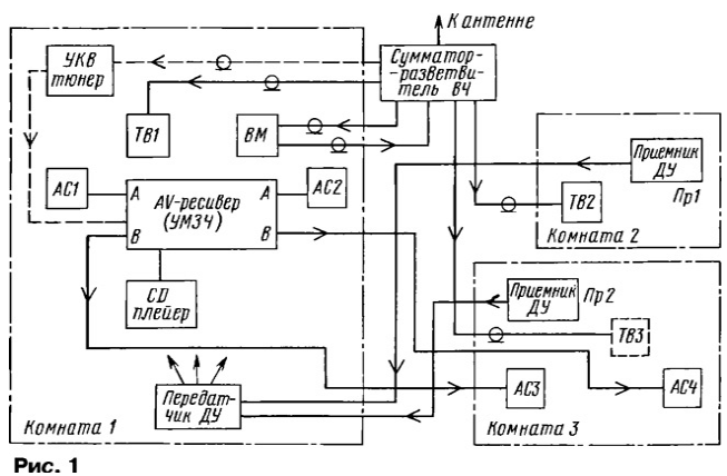
How to organize a simple multi-room complex will be discussed. One of properties of its components shown in Fig. 1. The complex consists of the system distributes audio and video signals and remote control.

Most simply realized audible alerts from your AV receiver (or USC) the speaker in the room 3. Connection cable may be a normal wire, used for wiring, the conductor cross-section not less than 0.75 mm2 (conversation, of course, not talking about Hi-Fi systems). Before wiring, you must mark one lived any icon, for example, "+", on both ends, then make it will be difficult. Connect the AC is necessary with respect polarity, otherwise it will be distorted stereo pan. In those cases, when an AV receiver (or USC) has no output "In" for the second pair of columns need to install external switch, which you can apply for tumblers high current (more than 6 A) circuits. They use reliable contacts with silver coating.
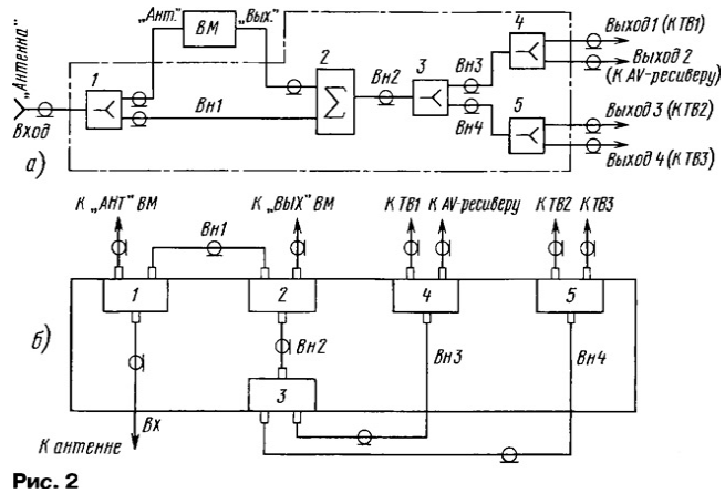
TV in rooms 2 and 3 are connected to a high frequency coaxial TV cable. When purchasing it you need to pay attention to the quality of the braid. It should be tight, without gaps, with copper, tin, and conductors. Connections are shown in Fig. 2 and the placement of the RF elements in Fig. 2,b.

To implement such a network will require broadband splitters 1, 3-5 and the adder 2. You can buy them at any radio or in stores that sell the radio components. They are made on ferrite rings and have small losses. Structurally they are most often collected in a box with three standard television sockets. When buying you must choose broadband products (MB - SCM) performance. By yourself'll need to make four cables internal connections (EXT), i.e. to solder the plugs to the sections of cable necessary length. For sale are the same hubs with the segment of the cable and plug on the entrance that can be used in positions 3-5. In this case, you need to make the cable VN.
The design of the device can be very different, right down to the placement of all parts inside the Cabinet for instrument or for him. The most convenient and simple to use for this purpose plastic box of suitable size. Need only sticking to the bottom of the splitter and combiner, pre-drilled holes for connectors. All connectors must be labeled.
A few words about the operation. Since VMS usually have an RF output in the UHF range, it is necessary to set the frequency of its internal oscillator to the signal VM does not interfere with the reception of local stations are UHF. Usually possible restructuring in the range from 36 to 42 channels (the setup procedure described in the instructions for the VM).
Television and УSW FM signals to the input device, proceed with the "antenna". In quotes written because in each case may be or broadband antenna, or two or three or more antennas, or the cable from the network in the house the entrance or others Often УSW FM signals to your AV receiver or tuner is served from a single antenna. The splitter 4 and the HD cable is not needed. But if TV only two, and don't need the splitter 5 and the cable VN. Options can be many.
Let us consider the main component of the multi - room complex devices do videoaudio-components (see Fig. 1), consisting of photodetectors in rooms 2, 3 and the transmitter in a room is 1. The operation of the device is very simple. Infrared photodetectors, located in rooms 2 and 3 react to command remote controls and form of pulse signals transmitted through the wires on the transmitter in the room 1, which generates an infrared flash that control all components of the complex.
In order to use VM in room 2, it is only necessary to insert the desired the cassette and then the remote VM implement any control commands VM. Similarly the relevant remote control components in the main room and from the room 3.
The easiest way for practical implementation of the multi-remote controller - use of modern industrial photodetectors constituting an integrated circuit of small size stirrup conclusions. Such detectors protected from external light and noise, and this fact is very important, as independent manufacture of the amplifier signals of the photodiode to provide high protection is not easy. Radio Amateurs of average skill in this case you can use the recommendations in the book of I. A. Ramazanova, A. V. Atsyukovsky "remote controls for household appliances" (M.: mark Print&publishers, 1999, pp. items 108 to 116), where diagrams are presented photodetectors and tips on them application.
Foreign companies produce a large number of integrated photodetectors. To unfortunately, the author does not have full background information on them, so the following presentation is based on information obtained experimentally.
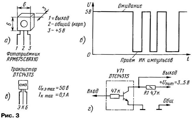
The photodetector RPM675CBRX10 applied in many VCRs firm MATSUSHITA (PANASONIC). His appearance, Pinout and waveform of the output signal it is shown in Fig. 3, a and b. This miniature sensor does not respond to various interference from visible light sources is quite large intensity (tested in a small room with two lamps of 150 watts). So to install it extremely simple, down to attaching adhesive tape to a wall, baseboard, etc. No other elements are not required. The connection to the transmitter is possible any wire length of 5 m. For greater distances may require the filing the output signal of the twisted pair.

The important question of where to purchase such a device. Currently they can be bought at radio, in stores and by mail through specialized firms mail order. Pictures photodetectors on the parcel agencies - in the range of 2... 10$. USA.
An alternative way is to use photodetectors that are in themselves TVs in rooms 2 and 3. In this case, you will need to do a little "research" work, why the need for an oscilloscope. Purpose - the polarity of the output pulses of the photodetector. They need to shoot through buffer amp. Easiest to do it on the transistor DTC143TS. It Pinout, parameters, and the switching circuit is presented in Fig. 3,b and G. the Transistor (price ≈ $ 0.25 USA) can be replaced by a transistor series KT315, etc. an external resistor in the base circuit impedance of 47 kOhm. Moreover, the resistor R1, it is shown in Fig. 3,g, can be placed outside of the TV.
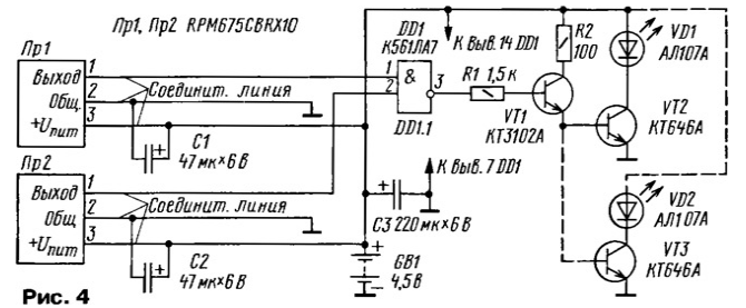
Schematic diagram of the entire control system is illustrated in Fig. 4. Photodetectors WP1, WP2 located in rooms 2 and 3 respectively. Blocking capacitors C1 and C2 soldered to the terminals of the photodetectors.

Power to the sensors is supplied from a battery of electrochemical cells, located in the transmitter (316, 343, etc.). Instead of GB1 battery can use and AC adapter. It should be noted that the entire device in standby mode (without command control) almost does not consume energy, E. battery will last a long time.
When submitting the command remote control apparatus using photodetectors and connective line inputs DD1 chip (pins 1, 2) come pulses with a magnitude of about 4.5 In, as shown in Fig. 3,6. In the chip they are inverted and through the emitter the follower transistor VT1 pass to the power amplifier transistor VT2, the load of which is the IR emitting diode VD1. Its radiation controls videoaudiogenerator in the room 1. It should be noted that while pressing buttons on the remote control in rooms 2 and 3, the device will not work. However such a situation is unlikely.
It is necessary to highlight some points of practical implementation. Before of all, it concerns the choice of photodetectors WP1 and WP2. Not every Amateur radio operator will be able to buy the photodetector, shown in Fig. 3 and 4. But the big problem with that you Can use most other more available. They are usually made in a small metal box with three conclusions and peep-hole for the phototransistor. Usually the sellers at radio nothing can't say about the parameters of the photodetectors.
So will have to deal with this issue, which will require oscilloscope, power supply voltage of 5 V and any remote control
First you need to determine the Pinout purchased photodetector. Conclusion common wire (building) it is usually connected to the screen. Connecting to it the negative conductor of the power source and the housing (Ls) of the oscilloscope, served voltage +5 V on any of the remaining conclusions of the photodetector through a resistor of 1 kOhm. To another output connected to the input of the oscilloscope, pointing the transmitter on the remote control of the "eye" of the photodetector serves any team. If pulses appear on the oscilloscope screen, Pinout (output and the output power is defined, if not, the conductors of the positive output of the source power and input of the oscilloscope swap.
In practice, of course, can be other situations, for example, in the case the build output stage of the photodetector on the open collector (runoff). While doing the same thing, but is fed to the input of the oscilloscope voltage +5 V through a resistor the resistance of 5-10 ohms.
In the process, see also the polarity of the output pulses of the photodetector. If it does not correspond shown in Fig. 3,b, at the transmitter tract the scheme in Fig. 4 need to add an additional inverter from DD1 chip (for example, with entrance from closed output 5, 6, and output - output 4).
In the further "research" to determine the sensitivity of the photodetector to external flashes, as well as the sensitivity to the signal at different positions on the remote control. On the basis of the results they find most convenient the location of the photodetectors in the rooms. Such action is performed in placing the transmitter in the room 1.
Before installing the system verify the performance of the device with the required the length of the connecting lines. If there is a particularly strong external interference you must use shielded wire for signal circuits.
To increase the zone of IR radiation it is possible to connect a second infrared emitting diode VD2 through the transistor VT3, as shown by the dashed line in Fig. 4.
Transistor KTA (VT2, VT3) can be replaced by 2SC1956Y 2SD1616, 2SD1781, 2SD1328, and diode AL 107A (VD1, VD2) is on the IR emitting diode from the AL or 156 EL-1L2, TS1Р7700, LN66A.
In conclusion the possibility of using such systems for remote control many other appliances, lighting, etc.
Author: J. Peter and Paul, Taganrog


