


")

Sometimes it is necessary to have the remote control panel device. If the number the buttons on it is large, to reduce the number of wires in connecting cable the remote is equipped with an encoding device, and the device - decoding. The problem can to simplify, if you decide to use the remote control with encoder joystick from the once popular consoles. These sticks contain eight buttons ("Turbo" button is not considered) and have five in the cable conductors.
Information about the interface between the joystick and game console known (see, for example, note S. Golubeva "Repair joystick "Dandy" in "Radio", 1996, № 6, p. 46). Information about pressed the buttons is transmitted in serial format using a clock signal from a controllable device. For synchronize the joystick has an entrance "Synchro" which served a short a pulse with logical high level after each cycle of obtaining data from joystick.
The proposed device, scheme of which is shown in the figure, is a decoder that converts the joystick signals to logic levels corresponding to pressed buttons. It consists of a pulse generator on the elements DD1.1, DD1.2, counter DD2, shift register DD3 and register storage DD4. The counter serves as for generating clock pulses intended for installation logic joystick in the initial state.
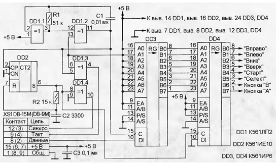
In the initial state (after the formation of the signal "Synchro") DD2 counter reset the joystick provides on-line data state of the first button ("A"). Data joystick served on the serial input register of the DD3. The pulse generator on the elements DD1.1 and DD1.2 shifts (V7) register DD3. The decay of pulses of negative polarity at the exit of the element DD1.3 joystick changes its state and provides information on the following button. Simultaneously with the information shift register DD3 increases the value in the counter DD2. After survey the last button ("Right") outputs of the register DD3 contain information about all the joystick buttons. The circuit R2C2 generates a short pulse, dropping DD2 counter and recording information from DD3 in the register storage DD4. From the output of the repeater on the element DD1.4, the sync pulse is fed to the joystick and translates it to its original state. After that the whole cycle repeats.
The generator on the elements DD1.1 and DD1.2 generates clock pulses with a frequency of approximately 1 kHz, which corresponds to the survey of buttons every 8 msec.
Depending on the connector on the joystick as XS1 use of computer socket DB-15M or DB-9M (the numbering of the contacts of the latter in parentheses). Feed the decoder and the joystick from a regulated source voltage of +5 V. Collected from undamaged parts and without error, the device does not require establishing.
Author: S. Kuleshov, Kurgan