


")

Many users of the various video equipment - TV, VCRs, camcorders - are faced with the problem of distribution television signals in the apartment. For this purpose, various filters, dividers, nets, etc. Hope that the material published here will be useful to our readers.
The number of consumers of a television signal in many apartments is constantly growing. The traditional TVs (and not one) and VCRs recent years have increased also computers that have video cards with TV tuner. At the same time increases and the number of television programmes, mainly due to the the opening of new commercial television stations in the UHF range. Set each receiver, its antenna uncomfortable.
So typical was the situation when a large number of TV signals having the different level, it is necessary to divide among many consumers. If the dividers to do passive, the reception of weak signals often becomes impossible. Therefore, we need active divider that provides signal distribution in the whole range of frequencies and operating without a loss or a small gain. Mandatory parameters of this divider should be low self noise and large dynamic range. This is because the levels take signals may differ from each other by an order of magnitude or more. If this neglected, possible loss of weak signals in noise or appearance crossover distortion in which the reception will be virtually impossible.
To solve this problem, we propose an active splitter, schematic diagram of which is shown in Fig. 1. It consists of a two-stage broadband amplifier transistors VT1. VT2 and divisor signals on hybrid couplers T1. T2. Frequency band of the transmission device 40 750… MHz. gain - 3…6 dB. The first amplifier stage is assembled on the low-noise transistor and the second transistor medium power, thanks the device has a low noise level and a relatively large the dynamic range. The input impedance of the transistor VT1 is greater than 75 Ohms and in the entire frequency interval is changed in 1.5…2 times. With a view to agreeing to it alignment and obtain values that are close to the characteristic impedance of the cable, the resistance of the resistor R1 is chosen to be 200 Ohms. At each of the four outputs the amplifier provides an undistorted voltage of 400 mV. Applied hybrid couplers provide isolation between the outputs is not worse than 10 dB in all frequency interval, which reduces the mutual influence of consumers ' signals.
Splitter can be powered from a regulated source in a separate the conductors or by a high-frequency cable. The first case is possible if near the device is a network socket. If not, then nourish it high frequency cable, changing the power supply circuit in accordance with the scheme in Fig. 2.
The supply voltage is served by cable, connected to the output 1. On the other end of the cable connect the dividing capacitor of about 100 PF and the point of its connection serves the supply voltage through the inductor inductance of about 100 mH. Supply current fanout of about 60 mA.
The device can be applied, except indicated in the diagram, the transistors CTA. CTA (VT1). CTA 2. CTV-2 (VT2); capacitors K10-17, CD. KLS: resistors MLT, S2-33, P1-4.
The transformers are wound folded in half and twisted wire sew-2 0.2 the ring of ferrite permeability 600…2000 and diameter 7… 10 mm. Winding contain ten turns should be evenly distributed throughout the ring. Coil L1 is wound the same way. but a single wire. The terminal of the resistor, capacitors and transformers shall have a minimum length.
All parts of the device are placed on the same side of the PCB from bilateral foil fiberglass, a drawing of which is shown in Fig. 3.
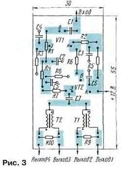
Second side (fully metallic) is a common wire. To the foil General wire solder the braid of the input and output coaxial cables, and through holes in the circuit Board - the findings of the details.
Mode constant current value is set automatically, and the building comes down to the correction of the frequency response selection of capacitor C4. It is desirable to obtain a small recovery response in the UHF range. that will offset the increased losses in coaxial the cable at these frequencies.
The stability of the amplifier will increase, if in series with the capacitor C7 to enable resistor 5… 15 Ohms.
Author: I. Nechaev, Kursk