


")

The signal from the microphone Ml type "Pine" through the capacitor C1 is supplied to the base of transistor VT1. Since the sensitivity of the amplifier of sound frequency is limited by the internal noise of the transistors, it is possible to reduce the noise in the first stages of the amplifier used low-noise transistors type KT3102.
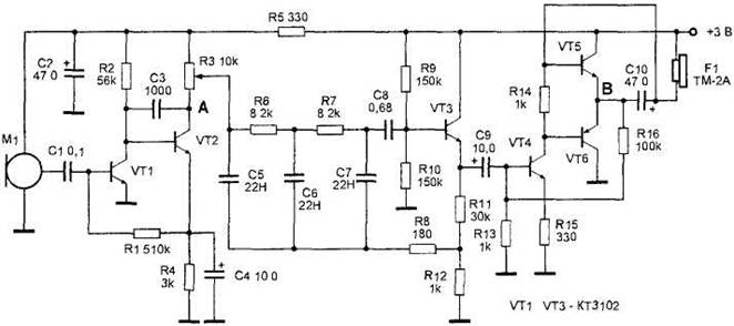
Figure 30. The microphone in low-noise transistors.
Amplifier cascades on transistors VT1 and VT2 by a deep negative feedback, which allows to ensure stable operation of the cascades and more linear frequency response. Load of the second amplifier stage is a variable resistor R3, and it is the volume control Complex RC filter consisting of the elements R3, C5, R6, C6, R7, C7 cuts out the "noise" RF components, received by the microphone, and leaves only the signals in the frequency band up to 4 kHz. This range provides maximum intelligibility of voice information
With the filter output signal is supplied to terminal amplifier audio frequency transistors VT4, VT5 KT315 type and the transistor VT6 type KT361. The load of the amplifier serves as a head phone type TM-2A or TEM. The resistors in the circuit are used such as MLT-0,125. Resistor R3 - SDR-41 or other small size.
Configuring the device is reduced to the selection of the resistances of resistors R1 and R16 to set the voltage at points A and b is equal to half the supply voltage.