


")

Below is a diagram of a remote microphone with power from the communication line. The device uses a dynamic or electromagnetic microphone. The gain of the voltage amplifier, assembled according to the diagram of figure 26, is about 3500. Signal transmission can be carried out on tens or hundreds of meters.
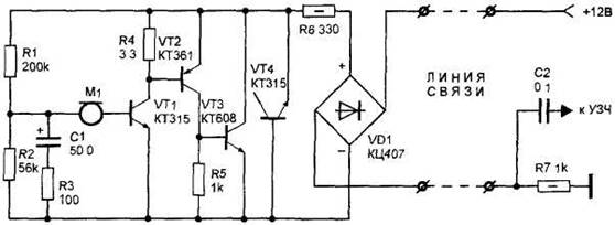
Figure 26. Remote microphone with power from the communication line.
The signal from the microphone M1 is supplied to the amplifier based on transistors VT1, VT2 and VT3. Between output and input of the amplifier introduced a negative feedback voltage formed by the resistors R1, R2, R3 and capacitor C1. In this case the initial current flowing through the amplifier circuit positive power source, a resistor R7, a constant and depends on the voltage of the power source and the resistance of the load resistor R7. The signal amplified by the amplifier, causes a change in the output current of the amplifier, which leads to a change of the load voltage. This voltage is supplied to the audio frequency amplifier through a capacitor C2. The amplifier of sound frequency can be used by any. The resistor R6 is need for harmonization in the internal resistance of the microphone amplifier to the resistance of the communication line. Rectifier bridge VD1 type CC necessary to prevent device failure due to incorrect connection of the power source. The transistor VT4, included as "analogue" of the Zener diode prevents voltage surges on the amplifier when I connect power. In addition, it provides symmetrical limiting of the output signal in case of overload of the amplifier, which eliminates the appearance of even harmonics, especially unpleasant for the ears.
The device uses type resistors MLT-0,125 (except R6 and R7). Transistors VT1, VT4 can be KT315 type, CT, CT, CT, KT3102. Transistor VT2 - KT361, CT, CT. Transistor VT3 - CT, CT, CT, CT, CT. Diode bridge VD1 can be replaced by four diodes type CD, CD.
Setup is to install the necessary gain by adjusting the resistance of resistor R3. When the resistance of the resistor R3 is from 0 to 20 ohms, you can get the gain from 3500 to 10.
The amplifier is powered from DC voltage from 12 to 60 V. the Current flowing through the device, should not exceed the limits of 0.5-60 mA. Its value is set by selection of the resistance R7.
If the resistance of the winding of the electromagnetic or dynamic microphone M1 DC less than 600 0m, it is desirable to include in the emitter circuit of the transistor VT1. As a communication line used shielded or regular wire. In the latter case, the wires are preferably recoiling among themselves.