Linkage analysis carried out for the year the work on 6 meters, has allowed to draw some conclusions that I want to share with the fans of the "magic band". Working from square KN89CW to the transceiver YAESY FT-736RDX with a power output of 10 watts, tried a variety of antennas, both vertical and horizontal polarization. 70% of relationships conducted through "sporadic"; 5% of ties held and Those reflected from layer Fz; 15% ties held "Tropo" and 10% - definitely hard to say, but most likely, probably manifested variations of Es and Those or and Fz. Most contacts made through Her and Fz. Kharkiv is located in the middle latitudes and, of course, the cloud over his head is not hanging - near zone is almost none. But the most interesting contacts were made, when the cloud was no closer than Italy. That is, at angles of approximately 8-10 degrees to the antenna D-130 (Discon firm "Diamont"). Thus on the horizontal dipole station almost barely audible.
Received QSL cards saw that my correspondents (top 30 according to the magazine DUBUS) use, as a rule, 5-6 el.Yagi or in rare cases 2x7 el. It became clear that the reflections from Her is a change of polarization. But unfortunately Yagi with a traverse length 1 ... 1.5 l (6 ... 9 meters) has an angle in a vertical plane 28 to 33 degrees, which is clearly not efficient for work on roads more than 2500 km. so, 10 watts, 7 watts is radiated into space. The real way out of the experience УSW, traverses the length 5l or 2х5l on 50 MHz does not pass, so how is it something about 30 meters. But unfortunately and narrow in the horizontal plane to be ineffective, as during the "sporadic" antenna not on spinning. The situation is slightly facilitated by the fact that in Russia the range of 50 MHz and yet, if we have a diagram in the horizontal plane 120-150 degrees and vertical to 10 degrees, the antenna can not twist. To satisfy these requirements? A little, for example, a 2-element phase vertical and ZL-beam, W8JK beam and hb9cv please with vertical polarization.
Research V. Polyakov (RA3AAE), driven SW-journal, antenna hb9cv please in General have long been known. In 1976 in the Swiss magazine "Old Man" and then in "Funkamator'e" No. 10-82 was published antenna HB9RU on VHF/UHF bands. Initially, the antenna HB9RU in the 80-ies is not attracted to me because of the work only vetically polarization (repeaters and grassroots communications FM at the time was not), but wisely deciding that 6 dB is not that bad. It's still a 4-fold increase in power. Due to the small size I took her to the cottage in the Crimea and the FT-11 almost daily I opened all the repeaters from Novorossiysk to Trabzon (Turkey). Counting the antenna on the 50 MHz, I realized - this is what you need. The material traverses - dural diameter of 30 mm. Elements are made of D-16T diameter 10 to 12 mm.

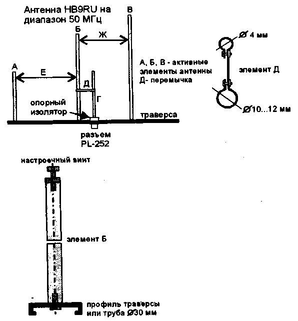
Fig.1
Fit the antenna into resonance on 50,150 kHz means of a brass screw MH, which is located in the top of the intermediate element. When specified on the drawing size, antenna on all bands is configured without problems. The presence of the reflector increased the antenna gain by about 1 dB, but decreased the influence of the mast, which is located behind the reflector. Therefore, the antenna, installing the mast can not be adjusted. A little later I found a use for this antenna and the ranges of 144 and 430 MHz, using them for communication via satellites: Fo-28. Fo-20. Uosat-14, Sunsat-35, Ao-27. Declared themselves HB9RU, such parameters of the antenna, as Kus = 5...7 dB and the ratio of forward/backward -15 dB was confirmed. The SWR on the bands when setting easily turns out to 1.1. Gamma harmonization is configured very simply, because, in spite of the half, the antenna under the beam "sees" your mirror image. Thanks, I had the opportunity not to clutter up the roof and install the antenna on the balcony and even to block the sector from Australia to Finland, i.e. 170 degrees. Conditional drawing of the antenna HB9RU is shown in Fig.1, and the dimensions for the three ranges of 50, 144 and 430 MHz summarized in table 1.
50 MHz
144 MHz
430 MHz
And
1146
380
126
B
1590
520
170
In
1839
610
203
G
405
135
45
D
135
45
15
E
510,6
170
56,6
W
862
287
95,6
For cross member can be used aluminum tube of 30 mm or aluminium profile. The linear sizes A - G are given in millimeters.
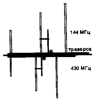
Antenna on 50 MHz is going on a separate traverse, and the ranges of 144 and 430 MHz are placed vertically one below the other, Fig.2.

Fig.2
Supply PL connectors are arranged horizontally, and the power cables can be removed in a spreader. The antenna was so compact that communication via satellites can be conducted by holding it in your hand. It may not be convenient, but on the FT-100 from the vehicle communication via UoSat-14 and SunSat-35 were carried out in pleasure. I will be very glad if my article will help you to discover a magical range of 50 MHz.
Author: A. Karakaplan, UY5ON Kharkov; Publication: N. Bolshakov, rf.atnn.ru


