


")

Automotive batteries are often charged devices with the current stabilizer. Proposed in this article, device and allows you to this case objectively determine the end of charging of the battery. Moreover, it will do this for an arbitrary shape and an average value of the charging current.
The end of the stable charging current is usually determined at the expiration of known period of time (the so-called charging time). However, in actually the charging current is changed due to the action of various destabilizing factors. Since the internal resistance of the batteries very few, even a small change in the charging voltage can cause a significant change in current.
On the other hand, the introduction of charger current stabilizer significantly complicates the design of the apparatus and reduces the efficiency. One way or otherwise, car chargers industrial manufacture, as a rule, do not provide stabilization of the charging current.
It is known that the battery is full, it is required to report a certain electric charge (quantity of electricity), is equal to the product charge time on the average current. In other words, the end of charging possible to determine the value communicated to the battery charge. The changes of current in the charging process will not affect the charge, and will only lead to an increase or to reduce charging times.
The need to measure the charge arises in other cases. For example, when the practice of charging is always necessary to know the capacity, which will be given to them upon discharge to the minimum allowable voltage. When perform a variety of electrochemical processes (for example, electroforming) also it is useful to measure the amount of electricity which has passed through solution.
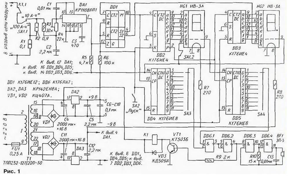
For measuring the charge passed through the measuring circuit, in terms of unstable current was developed device described below. It a schematic diagram is shown in Fig. 1.
(click to enlarge)
The unit Converter voltage to frequency integrated into a chip DA1. The voltage at its input, proportional to the charging current, is supplied with current sense resistors R1, R2 (either one or both, depending on the switch SA1 limit the measurement). Since the transformation function is linear, the output frequency circuits DA1 is directly proportional to the charging current. Work integrated Converter CRP described in detail in the literature [1,2]. so here omitted.
The output pulse voltage of the inverter is input to the divider frequency DD1. The frequency of the input pulses it reduces 32768·60 = 1 966 080. The conversion factor and the division ratio of the frequency selected such that when the voltage at the inverter input 1 To output pulse of the counter followed with the interval of 0.1 h (or 360). In other words, one pulse at the output of the counter corresponds passed through the measuring circuit to the electric charge 0.1 Ah. when the contacts of switch SA1 open, or 1 A·h when closed.
A simple calculation allows to determine the required conversion factor: 1966080/360=5461 Hz/V. Since this frequency is significantly (more than 50 times) exceeds 100 Hz. conversion error in the measurement of the charge transferred pulsating (after depolymerizing straightening) current must be minor, which was confirmed experimentally.
Duratray binary-decimal pulse counter, formed on the two counters modulo 10 DD2. DD3 digital indicators HG1. HG2. counts the number ampere-hours or tenths. Decimal point indicator included in HG1 mode 10 A·h", the decimal point indicator HG2 flashes when the flow the charging current in the load circuit and the more, the higher the current.
To set tripping torque source of charging current flow after a predetermined charge to the device installation unit consisting of two decimal counters-decoders DD4. DD5. switches SA3, and SA4 logical node on the elements DD6.1. DD6.2.
The state change counters DD2 - DD5 occurs on the falling edge of the input pulses, and setting the initial state of a supply voltage high-level input R.
In the measurement mode of the charge switches SA3 and SA4 establish the required the value of the charge, the switch SA1 choose the capacity of the counter 10 A·h" or "100 A·h" (division of LSB counter 0.1 or 1 A·h, respectively). Entrance include gap in the load circuit in accordance with a scheme submitted in Fig. 2, and serves on the device voltage and close the contacts of switch SA2 "Start".
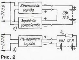
This figure shows a functional diagram of an apparatus for measuring the amount of electricity reported rechargeable battery GB1. At the same the scheme assemble the set-up for electrochemical process.
After some time on the outputs of counters DD4. DD5. who will be connected to the movable contact of the switch SA3, SA4. appears the voltage a high level. This level will occur at the output of the element DD6.2. In the result, in the first place. will start working generator configured on the elements DD6.3. DD6.4 generating the pulse sequence frequency of about 2 kHz. and the sound emitter BF1 gives a signal indicating that using rechargeable the battery has leaked a given amount of electricity.
Secondly, opens the transistor VT1 and work electromagnetic relay K1, contacts To 1.1 which, Rusakovich, disconnect the load. In this state the installation will be up until then. until it is disconnected from the network.
Measuring the charge is powered by a bipolar voltage regulator 2x9 V. made on chips DA2, DA3. Step-down mains transformer T1 - unified from the chamber of Commerce. Capacitors C6-C10. protecting circuits devices from interference, install one by one about each of the circuits DD1 - DD5.
At a voltage of 1 V on the inverter input voltage-frequency decimal point indicator HG2 included with a period of about 3 seconds to indicate that the current flow through the load circuit. More than this current. the more often the inclusion of a point.
Filament cathode fluorescent indicators HG1 and HG2 are supplied from sub-zero shoulder the stabilizer. This was done to increase the voltage difference between the anode - elements and the cathode of the indicator, which gives the opportunity to increase brightness the scoreboard. Fluorescent indicators in measuring eat low voltage (passport voltage 20…30 V), so their anodes elements connected to the outputs of counters CIE directly without additional transistors.
Instead YVES-FOR suitable indicators IV-b, but they are larger and consume more the filament current of the cathode, so you will need to pick up resistors R7. The R8. Transistor VT1 - any low-power silicon structure n-p-n (for example, from the series CT, KT315, CT, CT). Diode bridges VD1, VD2 - any of a series KTS402-KTS405: diode VD3 - also, any of the series KD KD, KD, KD, KD521, KD522.
Capacitors C4, C11 - oxide. C50-16 or K50-35; C3 - ceramic (km-4. Km-5. K10-7V. To 10-47) or mica, and he must have a small TKE (IGOS), because on this depends the stability of the conversion factor; other - of any type, the Resistor R1 consists of two parallel connected C5 - 16V the nominal value of 0.2 Ohms and a power of 5 watts. It can be made independently of cut thick wire of high resistance. The trimmer R4 - multi-SP5-2; other - MLT, S2-23 C2-33, and R2 is composed of two resistors connected in parallel (for example, with values of 1 and 10 Ohms).
The relay K1 is used to import. Best BS902CS (its winding has a resistance 500 Ohms. the contacts are designed for switching AC and DC current up to 10 A at a voltage of 220 V) It has the dimensions HH mm. Appropriate domestic relay for measuring the charge can pick up from the automotive group [3].
Transformer TP-127/220-50 can be replaced by any of a number of TLL) -127/220-50-TPP-127/220-50. thus it is necessary to connect the secondary winding thus, in order to diode bridges VD1 and VD2 received voltage 12… 15 V. Mains transformer can be manufactured independently. It is wound on tape magnetic SLH Winding I contains 2400 turns of PEV-1 0.08. winding II and III - 140 turns of PEV-1 0.25.
Sound piezoelectric emitter BF1 - any of a series of SN. The switch SA1 - P2T or another, with a current capacity of at least 5 A; SA2 - any. Disk switches SA3 - MPN-1.
Measuring the charge collected in plastic case dimensions HH Details mm. placed on two boards of the PCB, the Assembly is mounted conductors. One of them has a size of 130 mm 190 attached to the bottom of the housing, installed the elements of T1. VD1. VD2. DA2. DA3, C4, C5, C11, C12, R1, R2, K1, BF1. The rest details soldered to the second circuit Board (h mm), screwed to the front panel Voltage stabilizers DAI. DA2 are mounted on a heat sink with cooling surface 30…40 cm2 each.
Calibrate the device in the following way. The input contacts of the meter include in break the load circuit according to the scheme of Fig. 2,and set the operating current is 1 A. the Contacts toggle switch SA1 must be in open position, and the toggle switch SA2 - closed. Measuring repeatedly the repetition period of the pulses at the output Converter DA1 (pin 7). a trimming resistor R4 install them sixth-timecountry period. Then check the accuracy of the six-minute period the pulses at the output M (pin 10) of counter DD1 and, if necessary, adjust the same resistor.
It should be noted that objectively establish the charge, which must take the battery if you know its real capacity and it is discharged to the lower the acceptable range.
To determine the battery capacity is harvested bit installation according to the scheme in Fig. 2.6.
Maximum DC current. which can pass through the input circuit in position 100A·h" switch SA1 - 10 A. and 10 And · h." - 1A. If the measured current is in the form of pulses (for example, when charging the battery batteries), the average current must be reduced to 6…7 A. otherwise the resistor R1 will overheat. When you open contacts of the toggle switch should not SA1ток to exceed 1 A.
Literature
Author: A. Evseev, Tula