


")

Along with traditional chargers, providing nominal the charging current of the battery (up to 10 A), widely used by motorists homemade low-power, and therefore, small-sized and light devices, solving particular problems.
Below are descriptions of two such structures. One of them is designed for the charging current up to 1.5 A. the Author offers stationary to install it on the car and connect to the terminals of the battery.
Second on the charging current of about 0.5 A - designed for battery maintenance when pauses in operation.
The described low-power AC charger is for charging automotive batteries small current. Structurally it designed for installation in a vehicle connectivity system of electrical equipment. Thus, you do not have to deploy charging the device and connect it to the battery, you just plug in.
This enables you to charge the car battery anywhere where there is access to a power of 220 V. in Parallel with the charging device allows the use of the car.
Diagram of the battery charger shown in Fig. 1.
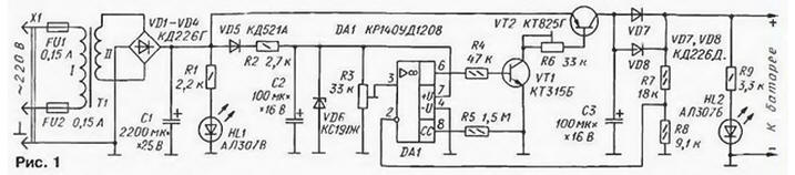
Oh DA1 monitors the voltage on the output of the device and at a fixed resistor R3 of the output voltage limits the current through the battery at the level of its current self-discharging. The capacitor C1 is designed to smooth fluctuations. When the current in 1.5 A voltage ripple is approximately 5 V. the Zener diode VD6 stabilizes the voltage of the OS. The resistor R6 serves to limit the charging current.
The voltage divider collected on the resistors R7 and R8 to the inverting input The shelter receives a voltage proportional to the output. The led is used for HL1 the indication of the voltage in the network, and HL2 - to indicate the connection the battery pack.
Due to the resistor R6 little charging current depends on the voltage on the battery, but when the set output voltage, the charging current is reduced to current value of its self-discharging. In this mode the device can work unlimited time, so to control the charging process is not necessary.
The device is also very sensitive to accidental shorting of the output circuit, but the long stay in this mode is undesirable. To protect the operator from electric shock applied three-wire network cable double insulation and plug X1 at the end. Of course, the protective contact response max must be securely grounded.
In case of accidental contact phase of the network to the vehicle body (due to damage network cable) burns out one of the fuses, the unit is de-energized. The secondary winding of the mains transformer T1 anyway must be securely isolated from the primary and from the magnetic core.
It must be remembered that when charging the battery in a random place, where Euro socket it may be ungrounded, you are putting yourself in real danger, so do not neglect any measures of protection (rubber Mat or dry Board under feet, rubber gloves or a dry cloth mittens).
The charger is structurally designed in a plastic box from shavers "Berdsk". The box I put under the hood of your car "VAZ 21063". attaching to an internal partition of the machine near the place for parts.
The transformer T1 is any compact network 25 W with secondary winding on the voltage 15.5 17.5… In at a current of 1.5 A. the Diodes VD1 - VD4. VD7, VD8 you can use any of a series of CD; possible replacement for CD CD and other average power. Diode VD5 - KD522. KD521 with any letter or other small-sized. Instead XJ suitable Zener COP E.
Led ALL green fluorescence can be replaced by ALG. ALGM. UNM. and ALB red glow - in ALC. ALBM. ALCM. Oh COD to replace COD. the resistor R5 is eliminated and the pin 8 is left free.
Transistor CTG mounted on the cooling plate with an area of 60 cm2 and 3 mm thick fixed resistors MLT, Podgainy resistors - SDR-38B. SDR-19 or other small-sized. The capacitors C50-35, K50-II C50-16.
Most of the parts of the device mounted on a printed circuit Board of foil fiberglass 1.5 mm the Drawing Board depicted in Fig. 2.
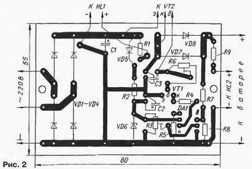
In the manufacture of the device for installation on the vehicle needs special attention should be paid to the stiffness of the massive installation of parts on the Board and other units and items in the box, as well as to protect the device from moisture and dust.
To establish the device connected to its output instead of the load voltmeter DC voltage and resistor R3 sets the voltage in the range 13.4… 13.6 V. Then, the output devices are connected sequentially discharged battery with ammeter and install a resistor R6 to the desired charging current within 0.5… 1.5 A.
Author: A. Korsakov, Orel
As is well known, automotive batteries during the long, for example, winter, storage, discharge, so they are recommended periodically to recharge. The described device is designed for automatic maintenance of automotive batteries in a charged state during storage. Its functionality compared to the set of equipment, described by the author in the article "Console-machine to a charger" ("Radio", 1997. No. 7. p. 44-46), more modest, but it is much simpler and does not contains Electromechanical relays.
Schematic diagram of the device depicted in Fig. 1.
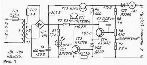
Transistors VT1, VT3, VT4 and the Zener diode VD5 form a series a voltage regulator. The voltage that the device supports on battery, install the resistor R6. The limits of change of this voltage is determined the resistance of resistors R5 and R7. The charging current is controlled on the scale of the ammeter RA1.
When the device is connected to the battery voltage on it usually less charging. Therefore, the control transistor VT3 is open and full, through it crosses the maximum current. To protect the regulating transistor from overload serves as a current limiter, assembled on the transistor VT2.
With increasing load current the voltage drop across current sense resistor R3 increases, and at some point the transistor VT2 is opened, reducing the base current of a compound of the regulating transistor VT1, VT3. As a result of the charging voltage, and hence the current through the transistor VT3 is reduced. Thus, the maximum possible current through the regulator - battery charging current battery - depends on the resistance of the resistor R3.
As the charging of the battery voltage on it increases, approaching voltage stabilization, and the charging current is reduced to the values required only to compensate for its self-discharging. Diode VD6 serves to protect the battery from discharge through the regulator circuits in the event of a power outage.
For rectifier charger included smoothing capacitor C1. He need not to reduce the ripple when charging, because, firstly, when as indicated on the diagram of the capacity of its smoothing effect will be noticeable only at very small charging current I. secondly, to smooth the charging current is generally not required. This capacitor allows adjustment of the output voltage the device - no pulsations at low load.
The inclusion of the device in the network is indicated by an led HL1.
The device is designed for continuous operation under stress without permanent supervision, therefore, to improve the reliability of the details of the selected reserve key parameters.
The transformer T1 will fit any with capacity of 20…25 watts. with a good winding the insulation for the secondary winding voltage 17…19B at a current of 0.5 A.
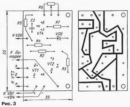
Fixed resistors, except for R3. - IFL; variable resistor R6 - PPV-1Z. Resistor R3 - wire, self-made (Fig. 2). He wound nichrome wire 3 with a diameter of 0.3 mm on a glass fibre laminate plate 2 with a thickness of 1 mm. since the nichrome poorly soldered, wire connection with brass findings 1 made by 4 screws with nuts M3.
Ammeter RA1 - anyone with a current full deflection 0.5…0.6 A. the Transistor VT3 and diode VD6 mounted on heat sinks area of not less than 100 and 10 cm2 respectively.
The device is mounted in a rugged casing sizes 170x120x90 front mm. the panel is withdrawn ammeter RA1. the indicator mains voltage HL1. holders fuses FU1 and FU2 and the handle of the resistor R6. In casing you need to drill ventilation openings.
Most small parts mounted on a circuit Board made of fiberglass 1 mm-thick Drawing Board shown in Fig. 3. In the drawing, the blackened areas where foil cutter removed.
Transistor P can be replaced by CTA, CTA or CT with any letter index; CTA - CTA or CT 15A; CTV - KT315B or CTG; CTSW - CTB. Instead A suitable Zener D, D, DA - DV.
Establishing device start with testing the limits of voltage regulation resistor R6. To do this, connect to the output of the temporary load resistor resistance 300 Ohm 1 watt. In the extreme positions of the resistor R6 engine the voltage at the emitter of the transistor VT3 must be equal and 13.8 16.8 V. When necessary, these limits are adjusted by the selection of resistors R5, R7. The scale under handle resistor R6 graduate from 13 to 16 In the exemplary voltmeter, connected in parallel with the load.
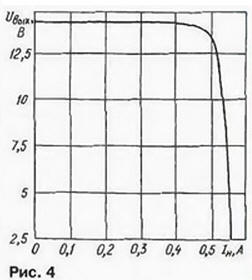
Picking up a length of wire of the resistor R3 sets the current through the boundary the stabilizer level is about 0.5 A. the Model the dependence of the output voltage stabilizer on the load current is presented in Fig. 4.
To charge the battery connected to the device in the appropriate polarity, install the resistor R6, the voltage that must have charged battery in accordance with the instructions for its use, and turn your device into the network.
Designing the device, should ensure a reliable insulation of live parts electrically connected to the network. And yet in operation apparatus, especially in the garage, should take all measures precautions to avoid electric shock.
Author: I. Herzen, Berezniki, Perm region.