Electronic voltage regulator in the automotive electrical system has already proven itself as a reliable, stable and durable unit. Below is described one of variants of such a regulator, for a long time run on different cars and had good results. Features of the controller are the use of a Schmitt trigger in the control node of the output transistor and the presence of the temperature dependence of the regulated voltage. The regulator is mounted in the housing of the relay control PP-380 and completely replaces it.
The first of these features is possible to reduce the power dissipation in the output transistor due to the high speed switching. The second allows you to automatically reduce the charging voltage of the battery when the temperature in the engine compartment. It is known that the charging voltage in the summer should be lower than in winter. Failure to do so leads to boiling of the electrolyte in the summer and nagasarete battery in the winter.
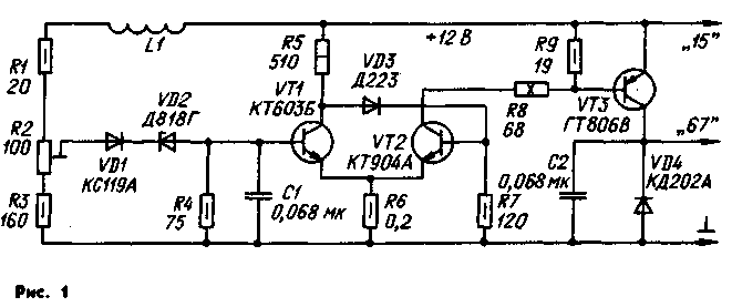
Schematic diagram of the electronic controller shown in Fig. 1. The controller consists of three functional units: the input control unit consisting of a resistive voltage divider R1-R3, stabistor Zener diode VD1 and VD2, Schmitt trigger transistors VT1.VT2 and the output key on the transistor VT3 and the diode VD4. The inductor L1 serves to reduce the voltage ripple at the input of the trigger that impair the effectiveness of regulation.

Elements VD1 and VD2 form the exemplary voltage. Supplied to the input of the Schmitt trigger voltage equal to the difference between the regulated part of the input voltage and exemplary. Due to the temperature dependence of the voltage on stabistor VD1 and emitterom switching transistor VT1 is reduced reference voltage with increasing temperature. As a result, the voltage applied to the battery, is reduced by about 10 mV with a temperature increase of 1°C, which is necessary for proper operation of the battery.
The Schmitt trigger is made according to the classical scheme. Capacitor C1 prevents the occurrence of high-frequency excitation of the transistor when it is in linear mode, and does not affect the switching speed of the trigger. The difference between the threshold voltage shift is determined by the ratio of the values of resistors R6 and R8, and is approximately 0,03 V.

The transistor VT3 of the electronic key is saturated in the open state, so that when the collector current of 3 And it falls by only 0.25 V. Due to the good performance of the transistor and the pulse control mode with a steep front and a decline of pulses of the control voltage power allocated to the transistor does not exceed 0.5 watts at medium and high speeds of the rotor of the generator and 0.8 W - low. With this power dissipation is absolutely necessary in the heat sink for the transistor VT3 no.
Diode VD4, serves to protect the transistor VT3 from surges of self-inductance winding of generator excitation arising in the closing moments of the transistor. The self-induction current is closed through the diode VD4, decreasing exponentially. The capacitor C2 removes the noise associated with the operation of the regulator and which can penetrate into the vehicle's electrical system.
Electronic regulator structurally conveniently carried out on the basis of the available relay control PP-380. With its base removed all the parts except the throttle wire and the resistor 19 Ohms, which is located under the mounting pad (this choke L1 in the diagram Fig. 1. a resistor R9). The plastic connector with the contact strips and the insulating gasket is also required to leave.
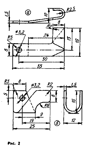
Most of the elements of the regulator is placed on two printed circuit boards made of foil fiberglass thickness 2 mm boards Outside the resistors R8 and R9, the inductor L1, the diode VD4 and the transistor VT3. The Board and the transistor VT3 is bolted to a square of sheet brass or steel with a thickness of 2 mm, fastened to the base by screws (with nuts) diode VD4(CDA). The drawing of a square are shown in tab. Diode VD4 installed in hole A.
Trimmer resistor R2 is installed on the Board 1 adjusting screw outward 'from the printed conductors. Transistor VT1 is glued in the hole Board 2. Resistor R8 - sew-10 - soldered pins to the two brass petals (Fig. 2, a and b), which is fixed by screws to the MOH in the holes of the base, which served as the controller of the PP-380 for attachment of 5.5 Ohms resistor.
Cost 1 details of the input node should be in the square after its fastening to the base. Then solder all the jumpers between the boards and the parts outside of the boards. The jumpers are made from tinned copper wire with a diameter of 0.5 mm.
The controller is used trimmer SP5-14; you can apply resistors and other values provided that the total resistance of R2+R3. The resistor R6 is made of wire of a wire with a diameter of about 0.3 mm, wound on a suitable resistor OMLT to 0.5. Instead of the resistor 68 Ohm (R8) it is permissible to use the same resistors 51 to 75 Ohms. Capacitors - km-5A-LEO, a capacitance of 0.1 μf.
Instead CTB you can use any transistor of the series, as well as CTA, CTB; instead CTA - CTB, CTA, CTB; instead GTV - any of the series GT, T.
When testing the controller instead of the transistor GTV was to sample the transistor PB. Although the warming up of the body of this transistor was slightly higher than that GTV, was quite acceptable use of transistors P. PA, PA - PV.
Stabistor XA can be replaced by XA. Instead DG you can use other Zener diodes in this series, however, may have difficulty with temperature regulator setting to overcome, which have to pick up the resistors R1 and R3 (keeping the total resistance R1+R2+R3 in the range of from 250 to 300 Ohms).
Instead A suitable diodes DA, DA, DB, CDA; instead KDA any of this series.
To establish the electronic controller can be directly on the car, but it's better to check first, is connected to the regulated power supply voltage to 14 V, with low ripple (with a span of less than 0.05). Before turning on the screw trimmer R2 to rotate in a clockwise direction, and the clamp 67 and GND connect an incandescent lamp (SM-20 or another) for a voltage of 12...27 In; Include a power source and rotate the screw resistor R2 counterclockwise to ignition of the lamp.
After that, the control is mounted on the vehicle. Voltmeter accuracy class not worse than 1.5 measure the voltage directly at the terminals of a battery. Before starting the engine check the voltage between the collector and emitter of the transistor VT3, it should be not more than 0.3 V. Start the engine, set the average speed of the generator rotor and the screw of the resistor R2 is adjusted, the voltage at the terminals of a battery to a desired level at 40 °C And 13.9...14 V, at 20 °C - ...14,2 14,3 V. for 0 - 14.4 14.5...V.
In conclusion, increase the frequency of rotation of the rotor of the generator to its maximum, the voltage at the terminals of the battery should be not more than 0.1...0.15 V. the Specified value is somewhat larger than provides the regulator, and due to the voltage drop on the wires and contacts in the circuit between the positive output of the battery and clip "15" voltage regulator. By the way, for this reason, when healthy, fully charged battery during the drive may experience a brief flash of warning lights on the dashboard of a car.
Multiple instances of the electronic controller have been tested for over 5 years and has shown good results. At an ambient temperature of +35 °C after reaching in the engine compartment of the maximum temperature (long drive) the voltage across the terminals of the battery decreased to 13.9 In, the charging current was equal to 0.7 A. the temperature is -10°C voltage increased to 14.4 V and the charging current was between 0.8...1 A.
Author: A. Korobkov, Lyubertsy; Publication: N. Bolshakov, rf.atnn.ru


