


")

Comprehensive engine management system consists of an engine management fuel injection "M1.3 and subsystem control of ignition on the basis of "LE-Jetronic". System Motronic 1.3" includes the electronic unit control (ECU), fuel pump relay-fuel pump, fuel distributor, injectors, pressure regulator fuel, idle speed regulator, meter, air flow sensor, throttle position sensor, coolant temperature, speed sensor crankshaft of the engine, the adsorber (a container of activated charcoal), vent valve, ignition coil, ignition distributor and spark plugs. The engine management system works as follows: the fuel pump through a fine filter delivers fuel to the fuel distributor. Further, the fuel supplied to the injectors mounted in the intake manifold of the engine, and through them into the combustion chambers (cylinders).
The fuel distributor is installed a pressure regulator fuel, which has a dependency on the vacuum in the intake tract and maintains optimum fuel pressure in the system. Air is supplied through the air filter into the intake tract, at the beginning of which is installed a flow meter of air. The flow meter readings of air are taken into account ECU to optimize the quality of the fuel mixture. The meter casing air flow rate may include additional air duct with the air supply regulator to bypass the main air path. This control within a narrow range, you can adjust the level of CO in the exhaust gases. Position sensor throttle is the main sensor, the readings of which are accounted for ECU to determine the quality of the fuel mixture. Additional air channel in the bypass throttle valve mounted with idling regulator serves to optimize the operation of the engine at idle. Managed by the controller idle through the electric component box control. The starting conditions of the engine are regulated ECU by means of level sensor coolant temperature. At the initial time of cold start of the engine is injected enriched fuel mixture.
The injection is performed three times during the first three revolutions of the crankshaft of the engine. After the engine starts the fuel injection is performed once for each revolution of the crankshaft of the engine. Ventilation of the fuel tank is carried out by means of the valve with adaptive control. Fuel tank fuel vapor through the adsorber (capacity of activated carbon) and the valve serves into the intake tract of the engine. The valve control is performed by the electronic unit control and depends on rpm and engine load. When you turn off the control voltage, the valve can be opened under the action of the vacuum in the intake tract of the engine. To prevent spontaneous ignition of fuel vapors after the ignition is switched off, the valve remains in control voltage (off) for a few more seconds. After that closed spring return valve and stops the access of pairs of fuel into the intake tract of the engine. The ignition timing is regulated by the ECU in response to a signal of the number of obratov crankshaft of the engine and, depending on the mode of operation of the engine.
Block diagram of the engine control system "Motronic 1.3"
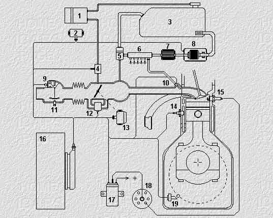
Fig. 1
1. The adsorber
2. Fuel pump relay
3. Fuel tank
4. Vent valve
5. the regulator of pressure of fuel
6. Drive fuel
7. Fuel filter
8. Fuel pump
9. Measuring the air flow rate
10. The injector
11. The air supply regulator
12. Idling speed controller
13. The throttle sensor
14. The coolant temperature sensor
15.Spark plug
16. The electronic unit management
17. Ignition coil
18. The ignition distributor
19. The rpm sensor crankshaft
Publication: www.cxem.net