


")

Comprehensive engine management system "Digifant" firm Volkswagen, consists of two subsystems: management fuel injection and control the ignition timing. The operation of all subsystems is controlled by the electronic controller, which is a specialized micro computer. Management subsystem injection fuel
The subsystem is responsible for the preparation of the fuel mixture and its supply to the engine. In this case, to each cylinder, the fuel mixture served by a separate nozzle. Works subsystem as follows: The fuel pump under a pressure of 2.5 kg/cm2, delivers fuel from the tank through the fuel filter to the fuel path and then to the injectors. At the end of the fuel path set pressure regulator fuel in the system, which maintains a constant pressure injection and implements the draining of excess fuel returning to the fuel tank, thereby circulating the fuel in the system and eliminates the formation in it of fuel vapor. Depending on the information received from the sensors installed on the engine, electrocentrale controls nozzles, thus, adjusting the amount of fuel mixture supplied to the cylinders. Thus, considering the amount and temperature of the intake air speed and the angle of crankshaft position, engine load and temperature its coolant. In addition, when the lambda probe, electrocentrale account and its information, such a way that optimally supports the content of harmful impurities in the exhaust the gases . The main parameter determining the dosage of fuel, is the volume the intake air. Coming through the filter airflow deflects to a certain angle pressure the valve, which is connected to a potentiometric sensor angle this damper.
The signal from the position sensor idle air control comes in electrocentrale, and it determines the quantity of fuel required in the moment and issue appropriate signals to control the opening of the injectors at the required time. Regardless of the position of the intake valves the fuel injection is performed twice for each revolution of the crankshaft. If the intake valve is closed, the fuel remains in the intake manifold until the next opening of the intake valve of the cylinder. The enrichment of the fuel mixture in the starting conditions can produced by supply of additional fuel the main nozzle, as for example in engines "RV" or more nozzles managed ocontroller, as in the engine "2E". When exceeding a predetermined engine speed and forced idle during electrocentrale terminates in nozzle control, thus, stopping the supply of fuel to the engine cylinders. Dosing the air supply when the start, warming up and is idling stabilisation valve idling.
Functional parameters
The fuel pump. Electric submersible inline fuel a pump. Installed in the fuel tank in one unit with the fuel level sensor. Brand and catalogue number: BOSCH 0 580 453 012. The fuel supply pressure to 3 kg/cm2. Performance when the voltage on the findings: - 9V: 275 cm3/30sec. 10V: 350 cm3/30sec. - 11b: 425 cm3/30sec. - 12V: 500 cm3/30sec. for all parameters +-cm/30sec.
The regulator of pressure of fuel. Regulator fuel pressure diaphragm type. Installed in the fuel path and serves to provide a constant fuel pressure in the system. Pressure regulation at idle: - when connected in a vacuum-tube: 2.5 kg/cm2; - when disconnected vacuum tube: 3.0 kg/cm2. Pressure calibration: +-0,2 kg/cm2. The residual pressure in the system after 10min. after turning off the fuel pump, not less than 2 kg/cm2.
Measuring the air flow. Measuring the air flow rate with a pressure disk for measuring the amount of air entering the engine. Potentiometric. Installed on the axis of the pressure disk, with integrated in the housing, a temperature sensor intake air resistive type and negative temperature coefficient (when the temperature the resistance decreases). Brand: BOSCH. Catalog numbers: the default setting is 0 280 200 241; part - 0 289 200 242. The potentiometric resistance of the sensor when measuring between pins connector meter air flow rate: - "3" and "4": 500-1000 ohms; - "2" and "3": smoothly varies depending on the position of the pressure disk. The resistance of the temperature sensor intake air measured between the conclusions "1" and "4" of the probe connector air flow rate and temperature of air: - 0C: 5,5+-0,7 K; - 20C: 2,5+-0,5 K; - 30C: 1,8+-0,2 K; - 50C: 0,8+-0,1 K; - 80C: 0,35+to -0.05 K; - 100C: 0,2+-0,025 ohms.
Sensor coolant temperature. Temperature sensor coolant in same type as the temperature sensor intake air and with the same characteristics.
Position sensors throttle
Option 1. Set the idling sensor and sensor full load. Both sensor positioner from - tion type. Installed on the axis of the throttle. Determine the mode of operation of the engine. The resistance of the sensor when idling gap 0.2 to 0.6 mm between the lever control ing the throttle and it stops idling - 0.5 Ohms. The resistance of the sensor full load at an angle of 10+-2 degrees between the throttle the dampers and chock full load - infinity.
Option 2. Position sensor throttle potentiometer type. Installed on the axis of the throttle. Voltage when measured between terminals "2" and "3" of the sensor connector: - when the throttle at full idle or full load: 0-0,5 V. - at intermediate throttle valve: 4.5 to 5.0 V.
The valve of stabilisation of idling. The air valve of stabilisation of idling electromagnetic, rotary type. Installed in the air path, parallel to the throttle body and provides the constancy of the speed of the engine at idle due to the change in flow area who stuffy channel.
Sensor oxygen content in the exhaust gases (lambda probe). The sensor delivers ocontroller information oxygen content in the exhaust the gases. Set on exhaust the manifold of the engine. Voltage - 12V. Output current - 0.5 to 3.0 A.
Management subsystem angle ignition
The main elements of the management subsystem angle of obregonia ignition are: ocontroller, switcher, built-in in the ignition distributor is the speed sensor engine (Hall sensor), built-in in the controller, the vacuum sensor, knock sensor, coil and spark plugs. Sensor detonation provides the load control unit La is the basis for regulation the ignition timing. The ignition timing is calculated by acontroller in direct proportion from punishment sensors and performs the ignition control.
Functional parameters
The ignition distributor. The ignition distributor with axial conclusions with built-in Hall sensor. Is ignition on cylinders, determine the number of revolutions of the engine and moments- the sparking. Catalog number: BOSCH 0 237 520 010. Initial ignition timing to TDC when you disconnected the sensor connector coolant temperature is 6 degrees +-18 sec. The output voltage of the Hall sensor when measuring between pins "4" and "6" connector switch - 0-2V. Rotor resistance of the Hall sensor Is 0.6 to 1.4 Ohms.
Switch. Catalog number: BOSCH 0 227 100 142
Ignition coil. Ignition coil with markings of gray or green. The resistance of the primary winding is 0.6 - 0.8 Ohms. The resistance of the secondary winding is 6.9 and 8.5 ohms.
The elements of the interference. The resistance of the filter resistor - 0.6 to 1.4 ohms. Resistance tip spark plugs - 4,0-6,0 ohms.
System block diagram engine control - "DIGIFANT"
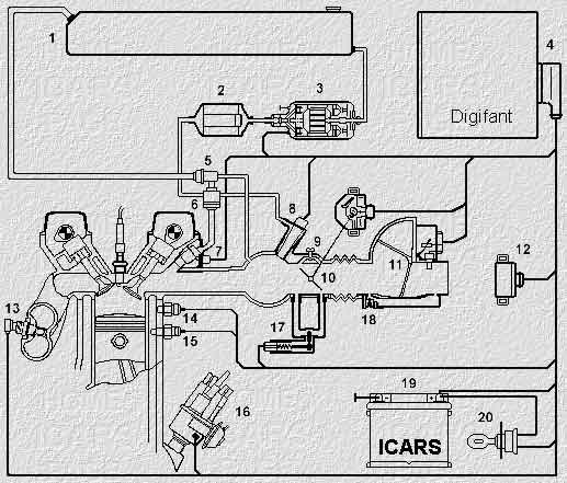
1. Fuel tank
2. Fuel filter
3. Fuel pump
4. The electronic control unit
5. The regulator of pressure of fuel
6. Drive fuel
7. The injector
8. Starting atomizer
9. The adjustment screw H. H.
10. The throttle
11. Measuring the air flow
12. Control relay
13. Lambda probe
14. Knock sensor
15. The coolant temperature sensor
16. The ignition distributor
17. Valve stabilize H. H.
18. The adjustment screw WITH
19. Battery
20. Ignition lock
Publication: www.cxem.net