


")

The fuel injection system "Motronic" is a combined system with distributed injection, i.e. at each cylinder has a separate atomizer. Each of the primary nozzles is controlled individually e-management unit. In addition, the intake manifold is installed extra starting the nozzle is controlled by the signal of the thermal relay. The injection system may include e-mechanical fuel pump, the fuel fine filter, accumulator-distributor fuel pressure regulator in the fuel system, fuel damper, the electronic control unit (ECU), idle speed regulator, injectors, filter nozzle, air flow meter, controls the angular position of the crankshaft, thermostats, temperature sensor, engine coolant, TDC sensor, controls, throttle position, ignition elements and control relays.
Operates the injection system (see Fig.1) to read as follows: fuel alnicos (2) through the filter of thin clearing of fuel (3) under pressure delivers fuel to the battery to the fuel distributor (4) and then to the injectors (11 and 12). At the end of the battery dispenser installed fuel pressure regulator in the fuel system (6) which ensures optimum fuel pressure, including the dependence on the vacuum in the intake tract of the engine. When exceeding needed at a particular point fuel pressure in the system, the pressure regulator through the fuel damper (5) returns excess fuel back to the fuel tank.
Due to the constant pressure and recirculation in the system excludes the possibility of the formation of fuel vapors. Mounted on the intake manifold in close proximity to the intake valves injector (11) provide good mixing. They are managed by an ECU according to a special program. The longer open the nozzle, the more enriched fuel mixture. The opening time of the injectors ECU is calculated based on the output signals of the sensors. Thus takes into account the temperature of the engine, the amount of intake air and its temperature, throttle position, engine speed. In addition, the control system can be incorporated feedback from lambda probe (18). When the sensor of the oxygen content in the exhaust gas (lambda probe), the ECU adjusts the mixing with the signals provided by the sensor. ECU stops the fuel supply to the engine cylinders, if I reach the limit of revolutions of the crankshaft and in overrun mode.
The number of revolutions of the crankshaft is controlled by the TDC sensor (23), and the angular position of the crankshaft corresponding sensor (24). The temperature of the engine ECU monitors the signals of the temperature sensor coolant (20), the air quantity signal of the flow meter intake air (16), and its temperature at the temperature sensor (17). The throttle is controlled by the signals of the sensor of angular position of the throttle (potentiometer) and switch its extreme position (15). When starting a cold engine on a signal thermostats (19) with additional nozzle (12), which is the enrichment of the mixture required for starting the engine. Due to the additional regulator air supply (21) supported speed of the crankshaft on the engine. The signals of the TDC sensor and a sensor of angular position of the crankshaft ECU controls the ignition timing.
Structural diagram of the fuel injection system "Motronic"
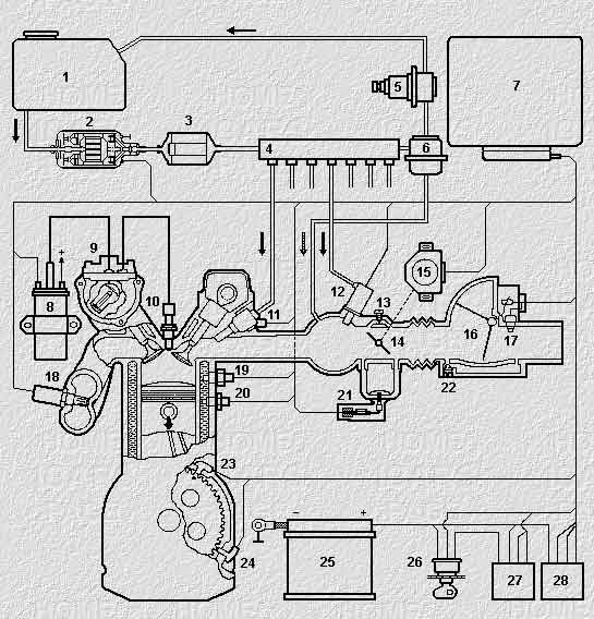
Fig. 1
1. Fuel tank
2. Fuel pump
3. Fuel filter
4. The fuel accumulator
5. Fuel damper
6. The regulator of pressure of fuel
7. The electronic unit management
8. Ignition coil
9. The ignition distributor
10. Spark plug
11. The injector
12. Starting atomizer
13. The mixture regulator
14. The throttle
15. The throttle sensors
16. Air mass meter
17. The air temperature sensor
18. Lambda probe (O2)
19. Thermostats
20. The coolant temperature sensor
21. Controller XX
22. The adjustment screw XX
23. The TDC sensor
24. The crankshaft position sensor
25. Battery
26. Ignition lock
27. Control relay
28. Relay fuel pump
Publication: www.cxem.net