


")

The system includes a fuel pump, the drive of the fuel, fuel filter, pressure regulator fuel in the system, the doser-dispenser fuel, electro-hydraulic control pressure regulator, an injector and a trigger nozzle, a Hall sensor, switch, throttle position, valve added airflow, coolant temperature sensor, thermal overload relay, potentiometer pressure disk, the electronic control unit. The fuel injection system operates as follows. The pump delivers fuel from the fuel tank to the dispenser-the dispenser of the injection system via the storage device and the fuel filter. In the dispenser-distributor, the fuel enters the upper chamber of the differential valves under pressure, it, in turn, depending on the position of the spreader, is adjusted by the pressure regulator of the fuel. The amount of fuel needed for cooking fuel mixture and fed to the injectors, is regulated by the diaphragm differential valves, which nestles managing pressure.
The fuel pressure in the system is determined by the relevant regulator, which sets the range of change of pressure in the system and adjusts the differential pressure. The control pressure regulator is a valve that is controlled, in turn, the electronic control unit. The controller includes a bimetallic plate from the position of which depends on the fuel supply to the controller. With increasing engine speed, the fuel supply to the controller is limited, and by reducing the speed increases.
The sensor signals the electronic control unit calculates the operation of the engine and produces control regulator valve control pressure. The additional valve air supply is controlled by the electronic control unit and operates during cold start and warming up of the engine. In starting conditions, depending on the temperature of the coolant, start the injector sprays fuel into the intake tract and provides enrichment of the fuel mixture for reliable starting of the engine. To ensure a more rational dispensing of fuel, the control system may include a sensor oxygen content in the exhaust gas (lambda probe).
In Fig. 1 is a block diagram of a control system of injection of fuel.
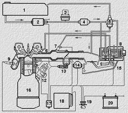
Fig. 1
1. Fuel tank
2. Fuel pump
3. Drive fuel
4. Fuel filter
5. The regulator of pressure of fuel
6. The injector
7. Starting atomizer
8. The doser-dispenser fuel
9. Lambda probe
10. Temperature sensor engine
11. Thermostats
12. The ignition distributor
13. The secondary air valve
14. The throttle sensor
15. Air mass meter
16. Engine
17. Control relay
18. The management electroblock
19. Ignition lock
20. Battery
Publication: www.cxem.net