


")

This unit plugs are of reliable performance at low temperature environment and a partially discharged battery, which is very important for a cold start of the engine in the winter, especially in Northern areas Russia. In addition, the block more noise, easy to establish and allows main controls.
The core of the device was widely known to radio Amateurs and enthusiasts block ignition G. Karasev described in [1], therefore here considered in detail only the nodes that have changed.
First, minor adjustments are made to the voltage Converter: added a voltage divider R3R4 (see scheme in Fig. 1), the capacitor C1 plus the output is connected to the midpoint of the divider and a Zener diode DB (VD4) replaced by DO with voltage stabilization V. 56 Is allowed to set the output the voltage selection resistor R3, instead of the Zener diode VD4 or the number of turns of the secondary winding of the transformer T1, as recommended in the description block Y. sverchkova [2] (which, incidentally, was used G. Karasev as source).
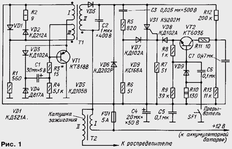
Now, when using the transformer T1 of the design presented in [1], the change of the resistance of the resistor R3 from zero to 30 Ohms can be installed on the inverter output any voltage in the range of 330…To 400 V. after add a voltage divider mode of operation of the transistor VT1 DC remained the same, the resistance of the resistor R1 is increased to 560 Ohms.
Has been completely re-knot forming pulses that control the opening the SCR VS1. Although the design of the site is complicated and increased the cost of its manufacturer, managed to improve the performance of the ignition module.
The site consists of a charge-discharge circuit (resistors R8, R9, Zener VD9, the capacitor C6), the switch current to the transistor VT2 and voltage divider Converter R12R13 with storage capacitor C7. Diode VD8 prevents charging of capacitor C6 through resistor R8. Current limiting resistor R11 can also be used to measure the collector current of the transistor VT2.
When the circuit breaker contacts SF1 capacitor C6 is charged by side through a resistor R9 to the voltage of the Zener voltage VD9. Since tripping of the breaker contacts, the capacitor C6 begins to discharge through the emitter junction of transistor VT2, diode VD8, managing the transition of SCR VS1 and a resistor R10. The transistor VT2 is opened, and the discharge pulse capacitor C7, charged to about 18, is fed to the control electrode of the SCR.
This schematic node generating control pulses selected not by coincidence. The fact that with decreasing ambient temperature or, more precisely, the housing temperature of the SCR current opening of SCR increases. For example, the current opening series triacs CU when the temperature changes from +20 to -40 o C increases 1.5 times. Often this is the reason that unit, worked smoothly in the summer, just refuses to work in the winter.
Experiments show [3] that the impulse current of 160 mA and a duration of 10 μs sufficient to open any of SCR series CU in the right temperature the housing -40°C. these pulses produces the described node formation. This eliminates the laborious and costly collection instance the SCR at a minimum temperature. Of course, if possible choose triacs, then it should use as "sensitive" SCR allows the use of a Zener diode VD3 at lower voltage stabilization - this will be discussed below.
The use of the Zener diode VD9 to limit the charging voltage of the capacitor C6 and the power collector circuit of the transistor VT2 from a regulated Converter voltage stabilizing the level of impulse control SCR in the starting time of the motor when the voltage of the battery from 7.5 to 14,2 V.
Reducing the voltage on the capacitor C6 has increased the immunity of the host pulse forming network and the ignition unit as a whole. This problem is usually considered tertiary, and in vain. If the influence of noise when you open contacts the breaker can be neglected, since the spark discharge caused by disturbance, will be to occur in the cylinder, where there is a working cycle, when the closed contacts can be failures in the engine.
But lowering the voltage on the capacitor C6 has led to the fact that the transistor VT2 when closed contact is closed a voltage equal to the difference between the the Board voltage and the voltage across the capacitor. In other words, to the transistor VT2 opened and there was a spark, the noise level must be more of this difference, without the Zener diode the voltage across capacitor C6 is equal to the Board voltage. It follows that the smaller the voltage stabilization the Zener VD9, the higher the immunity of the ignition module.
Capacitors C4 and C5 are used for additional protection against harmful interference in a block the on-Board network.
Resistor R10 determines the current through the breaker contacts. This current for self-cleaning contacts should not be too small. It is chosen usually in the range of 0,1…0,2 A.
Circuit pulse forming network for a multi-spark mode (diode VD6, VD7, resistors R5, R6, capacitor C3) is unchanged, except increasing the resistance of the resistor R6 to 51 Ohms. This is done to align voltage of the first pulse "multi-strike" circuit with pulses of node formation.
Here it is appropriate to dwell on the now prevailing opinion about the futility and even hazard multi-spark ignition mode. In my opinion, this view is mistaken, as during long-term operation of unit multi-spark ignition nothing but light and start the engine, increase power and economy the engine, reduce the content of carbon monoxide in the exhaust gases, is not seen". With regard to increased erosion candles, given the advantages of multi-strike ignition, it should be put up.
Multi-strike ignition can be harmful only if sparking continues throughout the time the opened state breaker contacts [4]. Then, indeed, there is a danger the occurrence of spark discharge in the engine cylinder, where the beat flows the compression. This can occur when the rotor of the distributor after opening contacts will turn to an angle greater than 45 degrees.
In the described ignition unit spark lasts about 0.9 MS and even the maximum rotational speed of the crankshaft of the engine is terminated long before the occurrence of a dangerous moment.
However, those who do not share my point of view, in the open circuit diode VD7 block to enter the switch. Then after you start the engine and warm it up, Razumkov circuit breaker, you can always switch to mode odnolistovoy work.
The ignition module used resistors MLT-0,125 (R1, R3, R9, R11, R13), MLT-2 (R10), MLT-1 (R12); resistor R2 is made up of two 18 Ohm 0.5 watts. Capacitors - MBM (C3), km or KLS (C5-C7), K50-6 (C4). Diodes KDA can be replaced by KD102B KDA, KDB. Instead CTB suitable transistors CTA, or CTA any of a series of CT.
The transformer T1 is assembled on the yoke SLH with non-magnetic gap of 0.25 mm in each of the three joints. Winding I contains 50 turns of wire sew-2 0,7, II - 450 turns, and III - 70 turns of wire PELSHO 0,17.
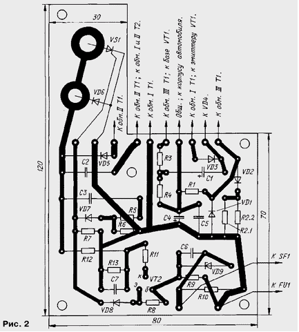
All the details of the ignition unit is housed in a durable metal box the size of 130x100x50 mm Circuit Board and the transformer is attached to the base of the box and transistor VT1 and a Zener diode VD4 - to its wall, which serves as their the heat sink. Fuse FU1 is placed either on the block or in another place.
Other parts mounted on a printed circuit Board made of foil fiberglass thickness of 1.5 mm. Drawing card is presented in Fig. 2. It is useful to recall here that the design and installation of the unit must comply with heavy conditions of operation - vibration, shock, humidity, water spray, fuel and oils, dust, wide temperature limits.
Establish a unit with an oscilloscope while connected to the ignition coil and igniting the spark. Powering the unit can be from any source of direct current voltage 8…15 V, capable of providing a load current up to 2 A.
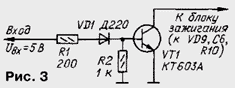
The breaker is convenient to replace makeshift console, the circuit is shown in Fig. 3. The input of the STB signal from the output of any generator sound frequency, and the collector of transistor VT1 is connected to the capacitor C6 node the generation of control pulses of the ignition module.
When the voltage of 14.2 V and a frequency of sparking 20 Hz pick resistor R3 in the range from zero to 30 Ohms (it is convenient to replace the variable resistor R3) so that the amplitude of the voltage across the primary winding of the ignition coil was in the range of 360 380…V. Then check the amplitude of the sawtooth the voltage across capacitor C7. If it goes beyond the 18…20 V, it is necessary to clarify the resistance of the resistor R13.
Sets the supply voltage 8 V, measure the voltage drop on Uу managing transition of SCR VS1 and the voltage drop UR11 on the resistor R11. Current opening SCR pulse is calculated by the formula
U.imp=UR11/R11-Uу/R7.
If the measured pulse parameters do not correspond to norm - current of 160 mA, the duration of not less than 10 μs at 0.7, choose a Zener diode VD9 so that its voltage stabilization was in the range of 5.6…8 V, and the capacitor C7 to obtain the necessary duration.
Then re-install the unit supply voltage of 14.2 In and check it out the performance over the whole range of the frequency of sparking, i.e. from 20 Hz to 200 Hz. Pulse current opening with increasing frequency decreases, and the reduction becomes noticeable only after 100 Hz. This is due to the fact that capacitors C6 and C7 do not have time to charge to a predetermined level.
Further increase the frequency of sparking to maximum Fmax, which the ignition unit stops working. The protection of pulses bounce closing of contacts is estimated according to the formula t s.Dr>1/2Fmax. According to [4] this time should not be less than 0.2 MS. Regulate the protection resistor selection R9.
When the value of the parts indicated in the diagram, the parameters of the ignition unit at a frequency of sparking 20 Hz, changes in the supply voltage from 8 to 14.2 must be In the following: the amplitude of the voltage at the Converter output - 360…380 V; current pulse opening of SCR - not less than 160 mA at a pulse duration not less than 10 μs at 0.7; the protection of pulses bounce contacts - not less than 1 MS. When the voltage of 14.2 V and a frequency of sparking 200 Hz current pulse opening of SCR decreased to 55 mA.
Fully assembled the ignition unit is installed under the hood of the car near the ignition coil. With the electrical system unit connect four wires of minimum length: two to the ignition coil, and the third to the housing, fourth - breaker.
The capacitor breaker must be disabled. For a quick return to the old variant of ignition in the event of failure of the electronic unit, it is desirable to provide special switch, as proposed in [1].
According to experts, when using multi-strike plug in the operational mode from the engine should not be expected to increase the output and efficiency, reduce the content of carbon monoxide in the exhaust the gases. Multi-strike ignition can only facilitate engine start in cold time of the year. Therefore, the installation of the switch in the open circuit diode VD7 block, as suggested by the author, should be recognized as appropriate.
Literature
Author: V. Yakovlev, Troitsk, Moscow region.