Currently many motorists are keen to devices electronic control of ignition timing (advance angle) or octane-corrector (s) that allow for 5...10% save fuel, to obtain maximum power, reduce emissions, and to adapt the engine to the fuel of varying quality. Existing schematics have some drawbacks:
- the delay is for a fixed period of time, the different revolutions of the motor shaft corresponds to a different ISP [1, 2];
- when you build circuits without delay fixed advance angle significantly increases their complexity [3, 4, 5].
With this in mind, we have developed a simple and effective QA, in which at any speed of the motor shaft the CPP remains constant. Block diagram of the QA shown in Fig. 1. The basis of his work laid the fact of proportionality delay the CPP period of rotation of the shaft. The sequence of pulses in which within certain limits is necessary to make the delay of the positive front, breaker is formed and fed to the input of the circuit.

The duration of the pause is used as the reference value, which is fixed by the reference oscillator G1 and reversible counter CT, which is at a low level at the input (±1) works to increase the account (the accumulation of information), and if you have the same input high level is decreasing (read the stored information). In the first case, running the generator G1 and the second generator G2 (and G1 is blocked). The frequency of G2 can be changed. In case of equal frequencies G1 and G2 delay the advance angle is 90°, therefore, to provide a delay of up to 30° is necessary that the frequency of G2 was three or more times higher than the frequency of G1. At the end of the account, when the counter gave all the information accumulated, at its output P signal is generated, which sets the output of RS flip-flop high level, blocks the operation of the counter and is detained output signal. In the initial state schema is returned with the parish at its input a low level, which resets the RS-flip-flop, and the cycle repeats.
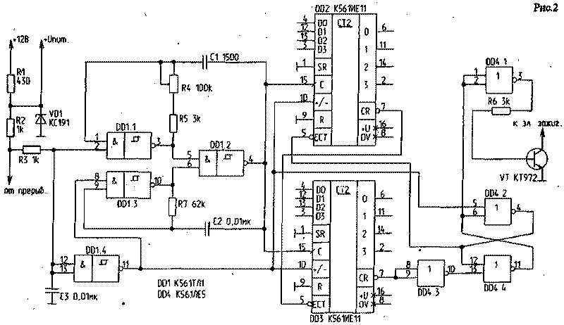
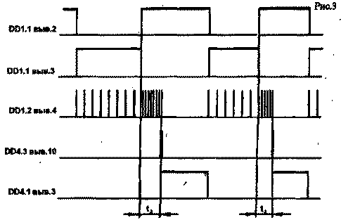
Schematic diagram of OK and the chart of its operation is shown in Fig.2 and Fig.3 respectively. At the input of the circuit has a filter of low frequency elements R3, C3, which together with cells DD1.1, DD1.4 with the input of the Schmitt trigger, eliminate the effects of contact bounce breaker on the circuit. Generator G1 is assembled on DD1.3, DD1.2, R7, and C2 to prevent the overflow of counters DD2, DD3 at low speeds of the motor shaft is configured for a frequency of 1 kHz. The generator G2 is assembled on DD1.1, DD1.2, R4, R5, C1 and a variable resistor R4 can change its frequency from 3 kHz to 90 kHz , resulting in adjustment of the advance angle from 30°C to 1°, respectively. Counters DD2, DD3 cascading, which increased their total capacity of up to 256 bits.

Fig.2
The counters first accumulate information about the duration of the closed state of the breaker contacts, and after their disconnection read it. When fully reset the counter at pin 7 DD3 appears short negative pulse through DD4.3 switches the RS-flip-flop collected for DD4.2, DD4.4. At the inverted output of the trigger signal is generated lock counter DD2 and through DD4.1, R6, VT-output the delayed signal.

Details:
Chip CTL can be replaced by C LA7, but after the low pass filter must be installed Schmitt trigger, assembled by any known scheme. The Zener diode VD1 - at any voltage 5...9 V. the Transistor CT can be replaced by a pair KT3102, KT815 (CT). Capacitors C1, C2, you must choose the same type with the same or as close as possible to the value zero, TKE. The same applies to the resistors R5, R7. Parallel to each chip on the power rails, it is desirable to install a ceramic capacitor of 0.1 UF, and in parallel VD1-tantalum electrolytic capacitor.
Setting
To configure the generator it is necessary to set probe frequency on pin 4 of the chip DD1. After that, the input of the circuit should file a logic low and pick up the resistor R7 so that the oscillator frequency was 1 kHz. Then set the slider of the resistor R4 to bottom in the diagram position, feeding a high logic level and pick up the resistor R5 so that the indications of frequency equal to 90 kHz , which corresponds to the delay of the advance angle of 1 °.
In the upper position of the slider R4 oscillator frequency should be about 3 kHz , which corresponds to the delay of the CPP 300. If desired, this value can be modified up or down by changing the value of R4. Now it remains to calibrate the scale of the resistor R4, which is mounted on the control panel. Wire it is desirable to screen.
Literature
1. Kowalski A., Frolov A. Console octane-corrector. Radio. - 1989.-№6.-C. 31.
2. V. sydorchuk E-octane-corrector. Radio. -1989. - No. 6. -31 C.
3. Bespalov, V. Corrector angle OZ. Radio. - 1988. - No. 5. - P. 17.
4. Arkhipov, Y. Digital controller of the ignition timing. Radioecology.-M.,1991.-S129.
5. Romanchuk A. Octane-corrector on CMOS chips. The ham radio. -1994 no.5.-C. 25.
Authors: V. Petik, V. Chemeris, Energodar; Publication: N. Bolshakov, rf.atnn.ru


